Hello,
The errors I get are coming from extraneous things. The errors are being caused by one error in one file that infects other files. The code that I know works as it compiles is now erroring out because of something in another file. I am attaching the clockdiv file, so you know what it is. sys_pll.vhd has the my_reset port because I need it for the equation in my process. I have a feeling though that that is not right.
I generated the IP, but I never got any code from it. I was unaware of that ability to take the template code. I learned about the IP from the youtube video and added it into the project as shown but did not know that I could take code from it that way. I thought it was a library that existed to help the compiler. I did not know what the top-level code was as I have no basis to go off of for the IP. So, the IP creates u0 and I need to make u1 for the sys_pll. Ok, I can do that. I copied the code the IP generated and I have:
u0 : component RRIP
port map (
ninit_done => CONNECTED_TO_ninit_done -- ninit_done.ninit_done
);
The CONNECTED_TO_ninit_done is not defined and is causing an error. This is not a signal, so how do I define this?
sys_clk and rst_in are variables I saw in the RRIP video, so I thought that they were needed. Perhaps I already have things defined and am creating redundant symbols. I would not put that past me. Locked is bidirectional as I saw it equaling itself i.e. locked => locked. I took it as this is a bidirectional pin.
With ninit_done being an output pin, I was under the impression that I would need an input pin for it as well to give data to something. If I cannot connect it to an input port, then I need an IF statement to say that it has changed? Or is there something else I can do?
The sys_rst is the flag saying that the system has reset that I saw on the video. Once I got my code running, I was going to use that as the checker to make sure the system reset. I thought that that was the point of it. I understand what the RRIP is supposed to do, but my ability to code it is far from perfect.
In the video they had the line locked => locked, so I thought that that was what I needed to do. It did not make sense to me either, but I trusted the video as it was from Intel. They should know their FPGA code is what I figured.
clockdiv is used for the main portion (sig.vhd) of the code to create a 25 MHz clock for the logic. The code will run on a frequency of 25 MHz.
I think I am slowly getting this as it is starting to make more sense now.
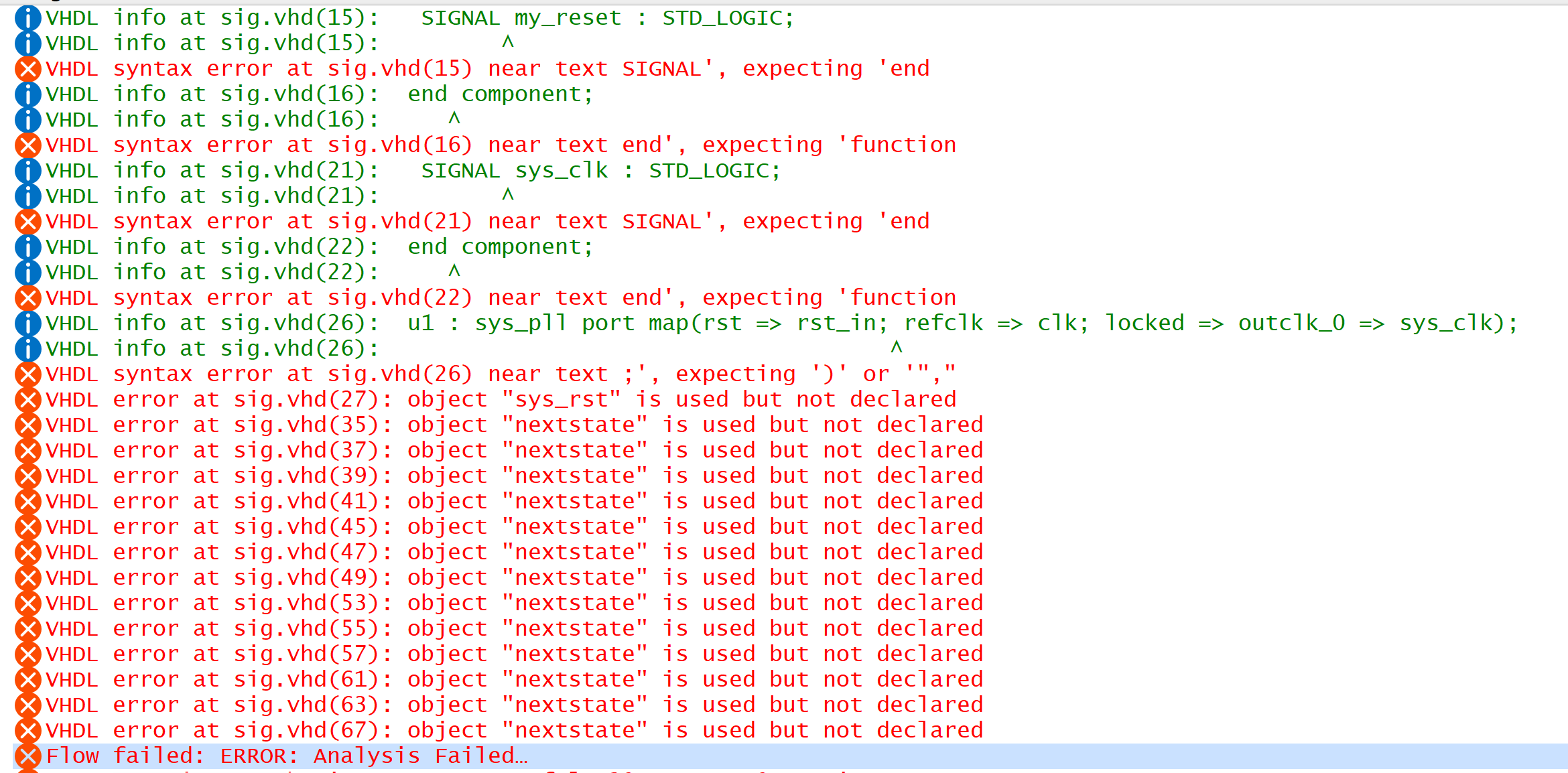
I did do the training, but it appears as though I need to go back through it. Oh boy. I am attaching the errors (meaningful errors) I am getting now and the code I have.
Thank you for your patience. I am trying my best to get this.
Drew
 Occasional Contributor

