Forum Discussion

 Occasional Contributor
Reset Release IP VHDL code not working
 3 years ago
By the way, here is how your project netlist looks like in the RTL viewer. You should really check the connections and make sure if this is what you intended.
The connections are easily changed through portmapping as I had helped you earlier. You may check out the VHDL trainings as it covers this.
It seems like a very small project. What are you trying to do with this project? Are you just going to run simulations? Are you going to do hardware programming?
Regards,
Nurina
 Occasional Contributor
Hello,
The errors I get are coming from extraneous things. The errors are being caused by one error in one file that infects other files. The code that I know works as it compiles is now erroring out because of something in another file. I am attaching the clockdiv file, so you know what it is. sys_pll.vhd has the my_reset port because I need it for the equation in my process. I have a feeling though that that is not right.
I generated the IP, but I never got any code from it. I was unaware of that ability to take the template code. I learned about the IP from the youtube video and added it into the project as shown but did not know that I could take code from it that way. I thought it was a library that existed to help the compiler. I did not know what the top-level code was as I have no basis to go off of for the IP. So, the IP creates u0 and I need to make u1 for the sys_pll. Ok, I can do that. I copied the code the IP generated and I have:
u0 : component RRIP
port map (
ninit_done => CONNECTED_TO_ninit_done -- ninit_done.ninit_done
);
The CONNECTED_TO_ninit_done is not defined and is causing an error. This is not a signal, so how do I define this?
sys_clk and rst_in are variables I saw in the RRIP video, so I thought that they were needed. Perhaps I already have things defined and am creating redundant symbols. I would not put that past me. Locked is bidirectional as I saw it equaling itself i.e. locked => locked. I took it as this is a bidirectional pin.
With ninit_done being an output pin, I was under the impression that I would need an input pin for it as well to give data to something. If I cannot connect it to an input port, then I need an IF statement to say that it has changed? Or is there something else I can do?
The sys_rst is the flag saying that the system has reset that I saw on the video. Once I got my code running, I was going to use that as the checker to make sure the system reset. I thought that that was the point of it. I understand what the RRIP is supposed to do, but my ability to code it is far from perfect.
In the video they had the line locked => locked, so I thought that that was what I needed to do. It did not make sense to me either, but I trusted the video as it was from Intel. They should know their FPGA code is what I figured.
clockdiv is used for the main portion (sig.vhd) of the code to create a 25 MHz clock for the logic. The code will run on a frequency of 25 MHz.
I think I am slowly getting this as it is starting to make more sense now.
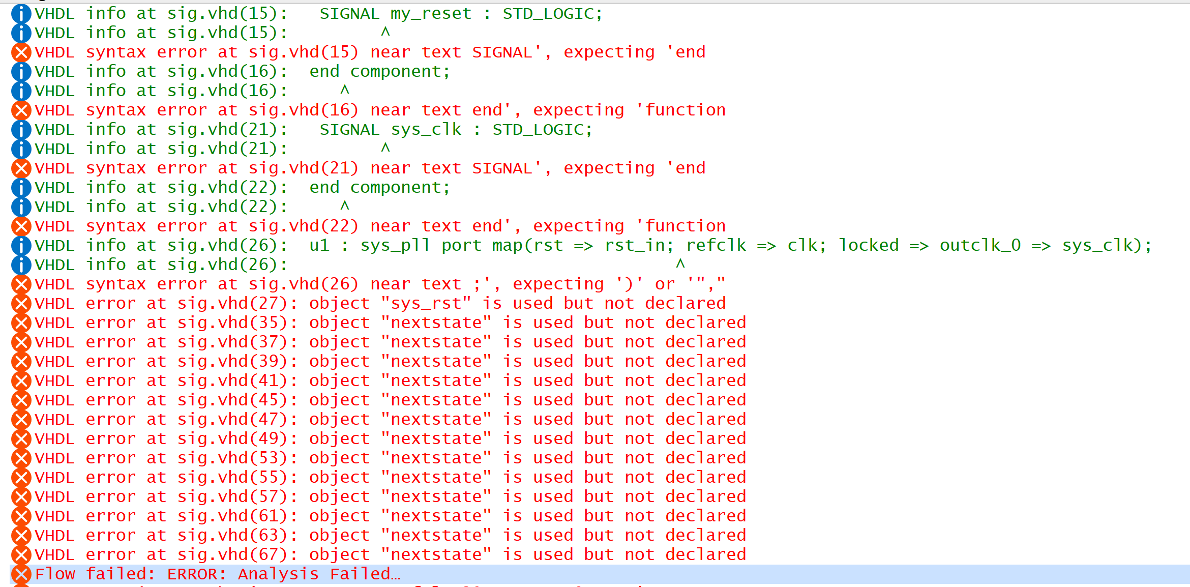
I did do the training, but it appears as though I need to go back through it. Oh boy. I am attaching the errors (meaningful errors) I am getting now and the code I have.
Thank you for your patience. I am trying my best to get this.
Drew

 Super Contributor
Lots happening here.
When you generate IP, it creates a number of files. You just don't need to interact with them usually. The generated code is placed in folders in your project directory (may be the instance name you gave to the IP or in an "ip" directory). It looks like you took the top-level file generated by the PLL IP and edited it (adding my_reset) which you should not do.
The template includes "CONNECTED_TO_..." to indicate where you need to edit it to replace it with the appropriate connection in your design. That's why it's just a template and not the final code you should be using.
ninit_done is an output signal of the IP, not an actual hardware output pin of the device. As such, you could certainly connect it to an output pin of the device to bring the signal out of the FPGA or connect it to the input of some other logic (like a reset input for example). This does not mean you can connect it to an actual hardware input pin of the device. As I stated previously, this makes no sense.
And as I suspected, clkdiv is not required. It's not clear if you need one or two clock domains, but you could just use the PLL to create the divided clock instead.
- MATRIX78783 years ago
Hello,
I did not use the PLL IP. The only IP I have is the Reset Release IP. Is that what you are calling the sys_pll? I did not know that that was to come from an IP. I thought that that was its own code chunk.
Can the template space be replaced with a signal? It would then need to change the direction of the => to <= if I am not mistaken. I do not think that making it ninit_done => ninit_done makes sense, so I need to create a new port for it. Is that right?
Ok, I think that the label is defined as a PORT and not a SIGNAL, so I might have misunderstood what it was trying to become. Ah, I see what you are saying. ninit_done is a software signal that talks within the software, it is not a hardware signal that I can connect to an LED. I can connect it to another software pin that can trigger a hardware function to turn on an LED if I desire, but I cannot use the signal directly. I think that was a big part of the problem I was having with understanding.
clkdiv is needed at least for the LED and switch control of the main program. That was the clock I had before I knew that I had to have a Reset Release. It would probably be best to have two clock domains, one for the reset and one for the main program.
Thank you and hopefully Nurina, has finished with my .qar soon,
Drew