Forum Discussion

 Honored Contributor
UART and MODELSIM ALTERA (code attached)
Hi dears.
I am trying to use a (slightly) modified version of the UART explained in a tutorial I've found, after reading some theory about. There is one UART entity which has two components - TX and RX, which in turn, operate with 9600bps in transmition and reception of bytes. The UART has two serial ports and two "parallel" ports for doing serial<->parallel conversion. The simulation results (for RX) can be visualized here: http://puu.sh/6tnpq/db6251b4ec.png My doubt: I am writing one byte 11111111 in the parallel_tx sign and I expect it to be passed to UART_RXD (not occurring in simulation). All the right sided signals are included in the sensitive list of all process as taught me here (the original code had not). I can't see any syntax erro on the codes (I had not noted any appointment in the comments where I took it from (Toni Axe, youtube)). note: I see that the RX and TX codes are written just with one process, with IFs operating as states (not using switch as I usually do). Any help will be appreciated (I created this post after 3 days trying to do it "by my self" in my DE2). thanks. PS: I am using 20000 ps clock period.29 Replies
 Altera_Forum
After some weeks I found the issue.
My first theory is that Altera boards just work with Altera codes (IP core). The code attached works very well in the Altera ModelSim simulation, but it does not in my DE2 (http://www.altera.com/education/univ/materials/boards/de2/unv-de2-board.html). If I am wrong, the Altera ModelSim and the Quartus II synthesizer/compiler are wrong too. My code is just a buffered RX 115200bps UART. I atacched even the pin csv association and my simulation results. When I send a byte via terminal, the TX led blinks indicating that the buffer is empty, but nothing more than that happens, even if I reset the system. I doubt if it has any error in the code. Thanks any way.- Altera_Forum
are rx and rd already synchronous to the 50MHz clock? if not, you need to synchronise them. If they are asynchronous you have the possibility of metastable registers in the real implementation.
- Altera_Forum
Yes, the mod_27_uart.vhd does that.
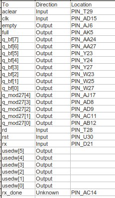
It takes 27 cicles from 50MHz and generates one pulse to RX. After 16 (oversampling) cicles, the RX consider to sample a byte. It means that the RX does sampling in the middle of each byte that comes in uart. For ease of implementation, the FIFO is a megafunction, so it may ensure that it works well in the project. I atacched a table showing pins association. I folow this calculation to convert 50Mhz to 115200bps: ------------------------------------------------------------------------------------------------------------------------------- 50 mhz (board) to 1.841mhz (uart 115200) In 115200bps, one bit is send in 0,000008681 seconds. If each bit is sampled 16 times, each sample must occur in 0,000000543 seconds. This is equivalent to say: 1841620,626151013 Hertz (1.841,620 MHz ~ 1.841 MHz) So, in one cicle of 50MHz, I need to wait 50MHz/1.841MHz cicles (or 27,1 ciclos) of 50MHz to read each of one 16 samples for each bit. ------------------------------------------------------------------------------------------------------------------------------- In resume, after 27 cicles from 50Mhz, I count one tick. After 16 ticks, I read a byte in TX. (Of course, for the first bit (start bit) I wait just 7 ticks.) - Altera_Forum
I mean the serial RX and rd inputs to the system. If they are not synchronised to the 50MHz clock externally then you will have problems sampling them inside ther FPGA. They need to be at least double registered to avoid metastability problems and glitching.
- Altera_Forum--- Quote Start --- I mean the serial RX and rd inputs to the system. If they are not synchronised to the 50MHz clock externally then you will have problems sampling them inside ther FPGA. They need to be at least double registered to avoid metastability problems and glitching. --- Quote End --- All the components are connected with the 50MHz clock from the board, as it can be seen in the schematic, through the "clk" inputs of each of the three components. As I am using the De2-70 ep2c70f896c6 Cyclone II, here (http://wiki.icmc.usp.br/images/0/04/de2-70-pins.txt)we can see the information about the pins of this board, i am using PIN_AD15 for 50MHz clock associated with the input named "clock_50MHz" in the schematic. This input is linked to the "clk" inputs of the three components. This "clk" input is the external 50MHz syncronization that the three components are using. Inside of mod_27_uart.vhd (http://www.alteraforum.com/forum/attachment.php?attachmentid=8640&d=1395413992) , I count the 27 cicles of 50MHz and generate one pulse to rx_uart.vhd (http://www.alteraforum.com/forum/attachment.php?attachmentid=8641&d=1395413997). In turn, the rx_uart.vhd (http://www.alteraforum.com/forum/attachment.php?attachmentid=8641&d=1395413997) counts 16 pulses comming from mod_27_uart.vhd (http://www.alteraforum.com/forum/attachment.php?attachmentid=8640&d=1395413992) to sample one bit (for start bit it counts just 8 pulses). All of them work with 50MHz.
- Altera_Forum
I am talking about the serial_rx and rd ports that come into the schematic. They are NOT synchronised into the 50MHz clock domain inside the FPGA. If they are not synchronised externally, you will run into problems on the board.
- Altera_Forum
Sorry, maybe I couldn't understand what you are trying to tell me, but,
I suppose that I am dealing with two clocks, 50MHz (board) and the frequency of the UART (1.8KHz approximate frequency when 115200bps). the uart signal comming from my PC is operating in 115200bps, so 1.8KHz, the RS-232 on the board is, I think, dealing with this signal in 1.8KHz. The RS-232 on the board sends the serial data to the FPGA pin UART_RXD (PIN_D21) in 1.8KHz. The FPGa and all the components in VHDL are working with 50MHz, trhough the pins "clk" in each component. The mod27 component converts the 50MHz clock signal to the ~1.8KHz clock signal including the oversampling of each bit of the data comming: The mod27 does it counting 27 cycles of 50MHz and generating one pulse. The Uart rx count 7 of these pulses and read the start bit from the first byte. The uart rx counts 16 of these pulses and read the rest of bits from the first byte. Why are they not syncronized inside FPGA if the "clk" input from them are conecteted to the 50MHz clock of the board? - Altera_Forum
You need to double register these 2 inputs using the 50MHz clock to prevent metastable events.
if serial_rx or rd have a rising edge the same time the 50mhz clock has a rising edge, then any registers sampling these signals will go meta stable, and so any other register may read it as 0 or 1 (depending on voltages). Using a double register prevents metastability, because the 2nd register will force and output of 0 or 1, and never meta-stable state. You need this double register synchroniser or your internal logic may have meta-stable events. - Altera_Forum
Really I got 5 warnings about time restrictions during the compilation.
These warnings say that I need to specify some restrictions in a SDC file before compiling. I am reading the following documentation from Altera: White Paper - Understanding Metastability in FPGAs http://www.altera.com/literature/wp/wp-01082-quartus-ii-metastability.pdf 14. Managing Metastability with the Quartus II Software http://www.altera.com/literature/hb/qts/qts_qii51018.pdf 7. The Quartus II TimeQuest Timing Analyzer Is that the way (TimeQuest Timing Analyzer) to correct the metastability using quartus II? I attached a TimeQuest screenshot where it tells me that I need specify a SDC file. The first and the second process in the TimeQuest are checked as we can see in the screenshot. Thanks. - Altera_Forum
No. You fix meta stability by inserting 2 registers on the serial_rx and rd inputs.