Forum Discussion

 New Contributor
Timing violation with Altera GPIO in DDR mode
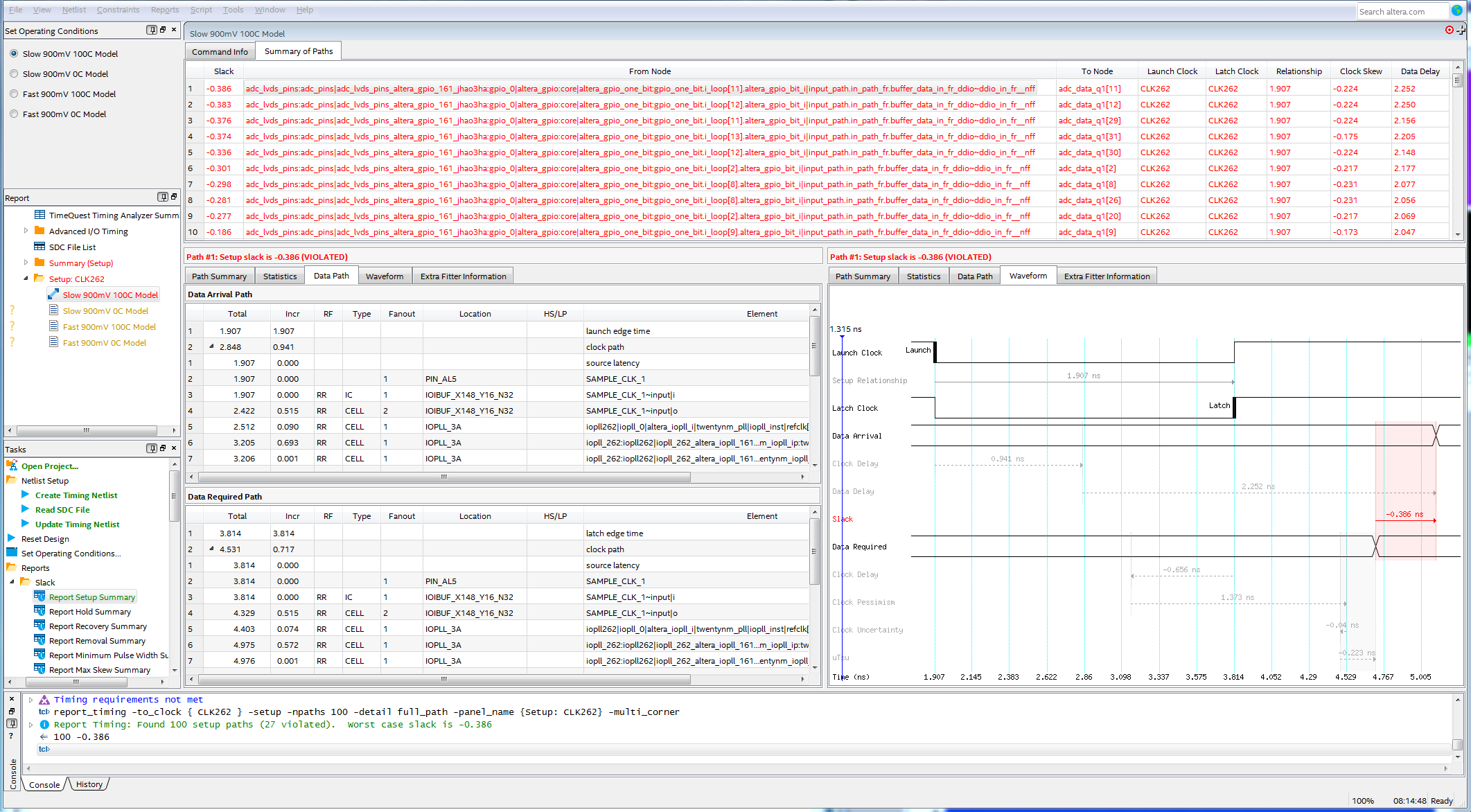
I have a setup violation at the register after the input register. The input register is constrained as described in AN433.
set_input_delay -add_delay -clock virt_adc_clk -min -0.6             [get_ports {ADC_DATA[*]}]
set_input_delay -add_delay -clock virt_adc_clk -min -0.6 -clock_fall [get_ports {ADC_DATA[*]}]

set_input_delay -add_delay -clock virt_adc_clk -max  0.6             [get_ports {ADC_DATA[*]}]
set_input_delay -add_delay -clock virt_adc_clk -max  0.6 -clock_fall [get_ports {ADC_DATA[*]}]

set_false_path -setup -fall_from [get_clocks virt_adc_clk] -rise_to \
[get_clocks CLK262]
set_false_path -setup -rise_from [get_clocks virt_adc_clk] -fall_to \
[get_clocks CLK262]
set_false_path -hold -rise_from [get_clocks virt_adc_clk] -rise_to \
[get_clocks CLK262]
set_false_path -hold -fall_from [get_clocks virt_adc_clk] -fall_to \
[get_clocks CLK262]
But now i have the violation after the input register, as you can see in the picture from Timequest.
Do I miss something?
33 Replies
 sstrell
Super Contributor
Can you show your clock constraints from the SDC?
#iwork4intel
 MRenn
Thank you for your answer.
I tried this:
create_clock -period "262.144 MHz" -name  virt_adc_clk
create_clock -period "262.144 MHz" -name  {SAMPLE_CLK_1} {SAMPLE_CLK_1}

create_generated_clock 	-name {CLK262} \
								-source [get_ports {SAMPLE_CLK_1}] \
								-divide_by 1 \
								-multiply_by 1 \
								-phase 90 \
   							-duty_cycle 50.00 { iopll262|iopll_0|altera_iopll_i|twentynm_pll|iopll_inst|outclk[0] }

derive_pll_clocks -create_base_clocks
and also this without phase shift:
create_clock -period "262.144 MHz" -name  virt_adc_clk
create_clock -period "262.144 MHz" -name  {SAMPLE_CLK_1} {SAMPLE_CLK_1}

create_generated_clock 	-name {CLK262} \
								-source [get_ports {SAMPLE_CLK_1}] \
								-divide_by 1 \
								-multiply_by 1 \
   							-duty_cycle 50.00 { iopll262|iopll_0|altera_iopll_i|twentynm_pll|iopll_inst|outclk[0] }

derive_pll_clocks -create_base_clocks
The violations are the same. For the appplication is no difference because we use the ADC AD9652 and we adjust the DCO by starting the system.
- sstrell
Get rid of the generated clock constraint. derive_pll_clocks does that for you. Also, is this edge-aligned or center-aligned? Instead of using -create_base_clocks, you need to have a create_clock constraint that properly defines the relationship between the virtual clock and the clock coming into the FPGA depending on that alignment using the -waveform option.
#iwork4intel
- MRenn
This is edge-aligned. I changed to your recommendations and now Quartus compiles the design. This will takes some hours.
create_clock -period "262.144 MHz" -name  virt_adc_clk -waveform {0.0 1.907}
create_clock -period "262.144 MHz" -name  {SAMPLE_CLK_1} {SAMPLE_CLK_1} -waveform {0.0 1.907}

derive_pll_clocks -create_base_clocks

set_input_delay -add_delay -clock virt_adc_clk -min -0.6             [get_ports {ADC_DATA[*]}]
set_input_delay -add_delay -clock virt_adc_clk -min -0.6 -clock_fall [get_ports {ADC_DATA[*]}]

set_input_delay -add_delay -clock virt_adc_clk -max  0.6             [get_ports {ADC_DATA[*]}]
set_input_delay -add_delay -clock virt_adc_clk -max  0.6 -clock_fall [get_ports {ADC_DATA[*]}]

set_false_path -setup -fall_from [get_clocks virt_adc_clk] -rise_to \
[get_clocks iopll262|iopll_0|adc_clk]
set_false_path -setup -rise_from [get_clocks virt_adc_clk] -fall_to \
[get_clocks iopll262|iopll_0|adc_clk]
set_false_path -hold -rise_from [get_clocks virt_adc_clk] -rise_to \
[get_clocks iopll262|iopll_0|adc_clk]
set_false_path -hold -fall_from [get_clocks virt_adc_clk] -fall_to \
[get_clocks iopll262|iopll_0|adc_clk]
Should I delete the -create_base_clocks? I thought I need it forc other PPLs.
- MRenn
- sstrell
Yes, get rid of create_base_clocks unless with "I thought I need it forc other PPLs." you mean that you have other PLLs in your design that are sourced from other input reference clocks. I'd still manually create all the base clocks, though.
#iwork4intel
- MRenn
I think I made a mistake with the settings of the PLL. I used -90° instead of 90° phase shift. With this and the assignments:
set_false_path -setup -fall_from [get_clocks virt_adc_clk] -rise_to \
[get_clocks iopll262|iopll_0|adc_clk]
set_false_path -setup -rise_from [get_clocks virt_adc_clk] -fall_to \
[get_clocks iopll262|iopll_0|adc_clk]
set_false_path -hold -rise_from [get_clocks virt_adc_clk] -rise_to \
[get_clocks iopll262|iopll_0|adc_clk]
set_false_path -hold -fall_from [get_clocks virt_adc_clk] -fall_to \
[get_clocks iopll262|iopll_0|adc_clk]
I cuttet the wrong transfers.
Now with 90° pase shift I also get slacks at the input registers.
I could not find the maximum achievable frequency for the LVDS DDIO GPIO with an Arria 10 10AS066H3F34I2SG. Where can I find it?
Please find the test design in the attachment.
Thank you for your help!
 KhaiChein_Y_Intel
Regular Contributor
Hi,
There is no qpf and qsf files in the QAR attached. Could you archive again? May I know what version of the software you are using?
Thanks.
- MRenn
Hi,
because of this issue we still use Quartus Prime 16.1.1 Build 200
https://www.intel.com/content/altera-www/global/en_us/index/support/support-resources/knowledge-base/ip/2019/why-is-the-last-output-frame-of-the-intel--fft-ip-core-missing-e.html
I manually added the qpf and qsf to the archive.
Thank you for your help.
- MRenn
Now I tested with 18.1. The Timing is the same, also slacks with setup and hold.