Forum Discussion

Altera_Forum's avatar
Altera_Forum
Icon for Honored Contributor rankHonored Contributor
15 years ago

The difference between the RTL level simulation and the Gate lavel simution

HI!

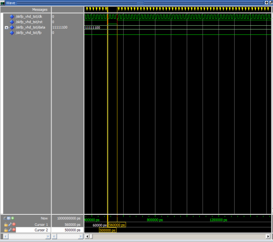
Everyone!

I am using Quartus ii web 9.1 . Now There is a problem between the RTL level simulation and Gate lavel simution. I need help!

this is the code:

LIBRARY IEEE;

USE IEEE.STD_LOGIC_1164.ALL;

USE IEEE.STD_LOGIC_ARITH.ALL;

USE IEEE.STD_LOGIC_UNSIGNED.ALL;

ENTITY SKFP IS

PORT(CLK : IN STD_LOGIC;

DATA: IN STD_LOGIC_VECTOR(7 DOWNTO 0);

FP : OUT STD_LOGIC

);

END ENTITY SKFP;

ARCHITECTURE ART OF SKFP IS

SIGNAL FULL: STD_LOGIC;

BEGIN

PROCESS(CLK)

VARIABLE COUNT:STD_LOGIC_VECTOR(7 DOWNTO 0);

BEGIN

IF CLK'EVENT AND CLK='1' THEN

IF COUNT="11111111" THEN

COUNT:=DATA;

FULL<='1';

ELSE

COUNT:=COUNT+1;

FULL<='0';

END IF;

END IF;

END PROCESS;

PROCESS(FULL)

VARIABLE TEMP: STD_LOGIC;

BEGIN

IF FULL'EVENT AND FULL='1' THEN

TEMP:=NOT TEMP;

IF TEMP='1' THEN

FP<='1';

ELSIF TEMP='0' THEN

FP<='0';

END IF;

END IF;

END PROCESS;

END ARCHITECTURE ART;

and this is the testbench:

-- Copyright (C) 1991-2009 Altera Corporation

-- Your use of Altera Corporation's design tools, logic functions

-- and other software and tools, and its AMPP partner logic

-- functions, and any output files from any of the foregoing

-- (including device programming or simulation files), and any

-- associated documentation or information are expressly subject

-- to the terms and conditions of the Altera Program License

-- Subscription Agreement, Altera MegaCore Function License

-- Agreement, or other applicable license agreement, including,

-- without limitation, that your use is for the sole purpose of

-- programming logic devices manufactured by Altera and sold by

-- Altera or its authorized distributors. Please refer to the

-- applicable agreement for further details.

-- ***************************************************************************

-- This file contains a Vhdl test bench template that is freely editable to

-- suit user's needs .Comments are provided in each section to help the user

-- fill out necessary details.

-- ***************************************************************************

-- Generated on "08/22/2010 20:56:38"

-- Vhdl Test Bench template for design : SKFP

--

-- Simulation tool : ModelSim-Altera (VHDL)

--

LIBRARY ieee;

USE ieee.std_logic_1164.all;

ENTITY SKFP_vhd_tst IS

END SKFP_vhd_tst;

ARCHITECTURE SKFP_arch OF SKFP_vhd_tst IS

-- constants

-- signals

CONSTANT NEWCLK:TIME:=20 NS;

SIGNAL CLK : STD_LOGIC;

SIGNAL DATA : STD_LOGIC_VECTOR(7 DOWNTO 0);

SIGNAL FP : STD_LOGIC;

COMPONENT SKFP

PORT (

CLK : IN STD_LOGIC;

DATA : IN STD_LOGIC_VECTOR(7 DOWNTO 0);

FP : OUT STD_LOGIC

);

END COMPONENT;

BEGIN

i1 : SKFP

PORT MAP (

-- list connections between master ports and signals

CLK => CLK,

DATA => DATA,

FP => FP

);

DATA<="11111100";

init : PROCESS

-- variable declarations

BEGIN

CLK <= '0';

WAIT FOR NEWCLK/2;

CLK <= '1';

WAIT FOR NEWCLK/2;

END PROCESS init;

END SKFP_arch;

The problem is, when I use the RTL level simulation, I found It's not right.

this is the simulation printscreen.

http://images.cnblogs.com/cnblogs_com/tdyizhen1314/257630/r_mo1.bmp

But when I use the Gate level simulation, and there is no problem.

the printscreen is:

http://images.cnblogs.com/cnblogs_com/tdyizhen1314/257630/r_mo2.bmp

Now I need help, Please tell me the difference!

thanks!
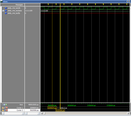
7 Replies

  • Altera_Forum's avatar
    Altera_Forum
    Icon for Honored Contributor rankHonored Contributor

    It's due the differences in initialization.

    In the RTL simulation, the registers are initialized to "X" or "U", since this is what the VHDL and Verilog specifications call for.

    In gate level simulation, the registers are initialized to "0", since this is what the FPGA actually does.

    There are two ways to handle this.

    1. You can specify initial values for the registers.

    2. You can add a reset signal to the module and make sure the testbench performs a reset at the beginning of the simulation.
  • Altera_Forum's avatar
    Altera_Forum
    Icon for Honored Contributor rankHonored Contributor

    It's normal simulation behaviour. The fp unknown state is copy from the variable temp in your design. While the gate level simulation reflects the default power on initialisation of registers, in functional simulation all signals are considered "unknown" unless you specify an initial value or use an explicite reset. This apllies at least to the variables temp and count.

  • Altera_Forum's avatar
    Altera_Forum
    Icon for Honored Contributor rankHonored Contributor

    rbugalho,

    Thanks for your reply.

    I tried before according to your method. It's OK to spcify initial values to the variables temp and count , But when I use an explicite reset(your second way) , there is still a question.

    This is the code After the modification:

    LIBRARY IEEE;

    USE IEEE.STD_LOGIC_1164.ALL;

    USE IEEE.STD_LOGIC_ARITH.ALL;

    USE IEEE.STD_LOGIC_UNSIGNED.ALL;

    ENTITY SKFP IS

    PORT(CLK : IN STD_LOGIC;

    RST : IN STD_LOGIC; -- '0' IS VALID

    DATA: IN STD_LOGIC_VECTOR(7 DOWNTO 0);

    FP : OUT STD_LOGIC

    );

    END ENTITY SKFP;

    ARCHITECTURE ART OF SKFP IS

    SIGNAL FULL: STD_LOGIC;

    BEGIN

    PROCESS(CLK,RST)

    VARIABLE COUNT:STD_LOGIC_VECTOR(7 DOWNTO 0);

    BEGIN

    IF RST='0' THEN

    FULL<='0';

    ELSE

    IF CLK'EVENT AND CLK='1' THEN

    IF COUNT="11111111" THEN

    COUNT:=DATA;

    FULL<='1';

    ELSE

    COUNT:=COUNT+1;

    FULL<='0';

    END IF;

    END IF;

    END IF;

    END PROCESS;

    PROCESS(FULL,RST)

    VARIABLE TEMP: STD_LOGIC;

    BEGIN

    IF RST='0' THEN

    FP<='0';

    ELSE

    IF FULL'EVENT AND FULL='1' THEN

    TEMP:=NOT TEMP;

    IF TEMP='1' THEN

    FP<='1';

    ELSIF TEMP='0' THEN

    FP<='0';

    END IF;

    END IF;

    END IF;

    END PROCESS;

    END ARCHITECTURE ART;

    and the testbench is:

    -- Copyright (C) 1991-2009 Altera Corporation

    -- Your use of Altera Corporation's design tools, logic functions

    -- and other software and tools, and its AMPP partner logic

    -- functions, and any output files from any of the foregoing

    -- (including device programming or simulation files), and any

    -- associated documentation or information are expressly subject

    -- to the terms and conditions of the Altera Program License

    -- Subscription Agreement, Altera MegaCore Function License

    -- Agreement, or other applicable license agreement, including,

    -- without limitation, that your use is for the sole purpose of

    -- programming logic devices manufactured by Altera and sold by

    -- Altera or its authorized distributors. Please refer to the

    -- applicable agreement for further details.

    -- ***************************************************************************

    -- This file contains a Vhdl test bench template that is freely editable to

    -- suit user's needs .Comments are provided in each section to help the user

    -- fill out necessary details.

    -- ***************************************************************************

    -- Generated on "08/23/2010 12:22:05"

    -- Vhdl Test Bench template for design : SKFP

    --

    -- Simulation tool : ModelSim-Altera (VHDL)

    --

    LIBRARY ieee;

    USE ieee.std_logic_1164.all;

    ENTITY SKFP_vhd_tst IS

    END SKFP_vhd_tst;

    ARCHITECTURE SKFP_arch OF SKFP_vhd_tst IS

    -- constants

    -- signals

    CONSTANT NEWCLK:TIME:=20 NS;

    SIGNAL CLK : STD_LOGIC;

    SIGNAL DATA : STD_LOGIC_VECTOR(7 DOWNTO 0);

    SIGNAL FP : STD_LOGIC;

    SIGNAL RST : STD_LOGIC;

    COMPONENT SKFP

    PORT (

    CLK : IN STD_LOGIC;

    DATA : IN STD_LOGIC_VECTOR(7 DOWNTO 0);

    FP : OUT STD_LOGIC;

    RST : IN STD_LOGIC

    );

    END COMPONENT;

    BEGIN

    i1 : SKFP

    PORT MAP (

    -- list connections between master ports and signals

    CLK => CLK,

    DATA => DATA,

    FP => FP,

    RST => RST

    );

    DATA<="11111100";

    RST_TEST:PROCESS

    BEGIN

    RST<='0';

    WAIT FOR NEWCLK*5;

    RST<='1';

    WAIT FOR NEWCLK*20;

    RST<='0';

    WAIT FOR NEWCLK*3;

    RST<='1';

    wait for newclk*500;

    END PROCESS RST_TEST;

    init : PROCESS

    -- variable declarations

    BEGIN

    CLK <= '0';

    WAIT FOR NEWCLK/2;

    CLK <= '1';

    WAIT FOR NEWCLK/2;

    END PROCESS init;

    END SKFP_arch;

    This is the printscreen:

    http://images.cnblogs.com/cnblogs_com/tdyizhen1314/257630/r_mo3.bmp
  • Altera_Forum's avatar
    Altera_Forum
    Icon for Honored Contributor rankHonored Contributor

    HI!

    FvM!

    I tried before according to your method. It's OK to spcify initial values to the variables temp and count , But when I use an explicite reset(your second way) , there is still a question. If you want to have a look about the details please see the reply above this.

    Thanks!
  • Altera_Forum's avatar
    Altera_Forum
    Icon for Honored Contributor rankHonored Contributor

    As I mentioned above, the variables temp and count needs initialization. Without resetting count to a defined value, your design won't work in RTL simulation.

    As a side remark. Your above design is using a ripple clock (the output of one process is used as a clock in another process). This is legal VHDL, but not recommended coding style, because it creates timing issues for other signals, that are fed from the first to the second process. You don't have them now, but most likely will in a more complex design.

    The problem and possible solutions ("clock enable method") have been discussed frequently in Altera forum and are covered by VHDL text books.
  • Altera_Forum's avatar
    Altera_Forum
    Icon for Honored Contributor rankHonored Contributor

    You are right. Maybe I didn't make the question clear before . as long as I spcify initial values to the variables temp and count . the RTL level simulation is OK .

    However, AS rbugalho said, " 2. You can add a reset signal to the module and make sure the testbench performs a reset at the beginning of the simulation."

    According to his method , I tried and I failed . this is the main problem which is bothering me all the time.

    PS: rbugalho is the first respondent to the topic.