video
69 Topics
Introducing the Altera Community AI Responder — Beta
Altera is introducing the AI Responder, an assistant built into the Altera Community to help provide faster, context-aware guidance for Altera product questions. It uses relevant public Altera documentation and Knowledge Database content, with coverage continuing to expand. The AI Responder may provide source references and can hand off complex or out-of-scope questions to an Altera subject-matter expert. As a beta feature, responses may contain errors or omissions, so please review the sources and verify technical guidance against official Altera documentation before implementation. If the response does not fully address your question, add more context and tag ai_responder to continue the discussion. We welcome your feedback as we improve the Community experience.24Views0likes1Comment
Agilex5 o_tx_ready and o_rx_ready not asserting
I'm working on a design for a video router, and having trouble with the transceivers. I have the premium devkit to test run the setup. This board has ES silicon, A5ED065BB32AE6SR0. The design would implement 4 or 8 lanes of 12.5Gbps (later 17Gbps or faster), on the GTS XCVR, PCS Direct with IEEE_FLEXE_66 implementation. I followed the User Guide to implement the startup sequence (Reset_Sequencer is OK - it handshakes src_rst_req and src_rst_grant). Figure 65 was my guideline to develop the FSM to bring the Tx and Rx lane up and running. The issue I'm observing: The TX run-time reset sequence (UG Fig 56) completes: i_tx_reset asserted → o_tx_reset_ack asserts → i_tx_reset deasserted → o_tx_pll_locked asserts → src_rs_grant completes. But o_tx_ready never asserts (o_rx_ready likewise). As an extra measure against metastability, all status signals are 2-flop synchronized before use. When I hook up the Transceiver Toolkit, it brings the same channel up reliably. What additional condition gates o_tx_ready that isn't in Figure 56, or what should I look for to get the XCVR reliable up and running. After the initial 'bring_up_sequence, I'll run 4kb packets at 64/66bit to minimize overhead, hence the FLEXE_66. I'm kind of stuck165Views0likes6CommentsVVP Protocol Converter Not work
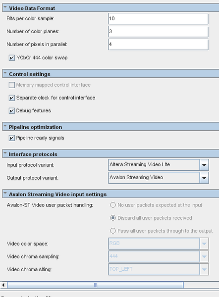
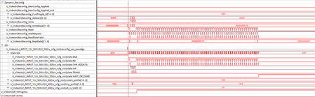
Hello, I am looking for how to use the VVP protocol converter, by converting Altera Stream Video Lite to Avalon Streaming Video. I generate a simple pipeline with Protocol Converter to Frame Buffer on Cyclone 10 GX... Here's the settings of the converter, And the Register settings for this IP, For unknown reason, I am unable able to see the protocol converter ready to work by setting rx ready signal goes "high" on STP. Even when the tx side ready signal is OK. Readback the register, the mode is fine and the CTRL is bit 0 is set already.. What would be wrong on my settings? Please help. Thank you.270Views0likes11Comments
GTS SDI II IP Core...what is the tx_vid_clkout frequency
I'm using an Agelix 5 (the Altera development board) with Quartus Pro 25.3.1 w/patch 1.02. i'm trying to set-up the GTS SDI II IP Core (version 2.3.0) on the Main screen, the only configurable values are: Video Standard = HD-SDI Direction = Transmitter Insert payload ID = off SDI_II wrapper = Both BASE and PHY everything else is grayed out. I have connected the tx_pll_refclk to the 148.5MHz input. I do see the tx_pll_locked signal behave as expected and it does lock. the problem is when I look at the tx_vid_clkout signal its 58.3MHz. I expected it to be 74.25MHz. I'm somewhat confused as to whether tx_pll_refclk should be 148.5MHz or 74.25MHz, but if the 148.5 is wrong then I would have expected tx_vid_clkout to be twice, not a somewhat random value of 58.3MHz. when I reconfigured the IP core for 3G-SDI, the tx_vid_clkout frequency doubled to 116MHz. The doubling would be what I expected, but still a wrong frequency. i'm not sure what i'm setting wrong and why i'm getting a clkout of 58.3MHz476Views0likes23Comments
Agilex‑7 F‑Tile Dynamic Reconfiguration Conflict Between HDMI and SDI RX
Hello, I am working on a design targeting an Agilex‑7 device (AGFB014R24C2I2V) using Quartus Prime Pro 23.2. The design includes two video RX interfaces on the same F‑Tile, both configured as input-only: HDMI (TMDS only) SDI‑12G Both IP cores use dynamic reconfiguration to adapt the transceiver to the detected input frequency: HDMI: Mixed single-rate PHY (63 profiles) SDI: Multi-rate PHY (4 profiles) Since both IPs are located in the same F‑Tile, they share: A single dynamic reconfiguration block (through the arbiter from the provided IP example) The same System PLL Observed Behavior When only one RX IP is instantiated (either HDMI or SDI), the link comes up correctly and video is received as expected. When both RX IPs are instantiated simultaneously: HDMI link initializes and operates correctly. SDI PHY fails to lock to the input signal. Debug Observations Using SignalTap on the dynamic reconfiguration interface: The SDI reconfiguration state machine cycles through all profiles. Each reconfiguration completes successfully (no errors reported). Despite this, the SDI RX never achieves lock. Suspected Cause This appears to be potentially related to a resource conflict or incorrect sharing configuration within the F‑Tile, possibly due to QSF assignments or transceiver resource allocation. However, the exact root cause is unclear, and I may be overlooking a configuration requirement for: Shared dynamic reconfiguration usage Multi‑client arbitration F‑Tile resource partitioning Additional Information Below are the QSF assignments used to configure the dynamic reconfiguration IP. For brevity, only the first and last HDMI profiles (out of 63) are included. # Configure global assignments for SytemPLL set_location_assignment PIN_BH8 -to REFCLKIN_HDMI_13A -comment "Pin Function Name is REFCLK_FGTR13A_Q0_RX_CH0P" set_location_assignment PIN_BJ7 -to "REFCLKIN_HDMI_13A(n)" set_instance_assignment -name IO_STANDARD "CURRENT MODE LOGIC (CML)" -to REFCLKIN_HDMI_13A -entity iWave_HelloWorld set_location_assignment PIN_BP8 -to REFCLKIN_100M_13A -comment "Pin Function Name is REFCLK_FGTR13A_Q1_RX_CH3P" set_location_assignment PIN_BN7 -to "REFCLKIN_100M_13A(n)" set_instance_assignment -name IO_STANDARD "CURRENT MODE LOGIC (CML)" -to REFCLKIN_100M_13A -entity iWave_HelloWorld set_location_assignment PIN_CJ7 -to REFCLKIN_148M5_13A -comment "Pin Function Name is REFCLK_FGTR13A_Q3_RX_CH6P" set_location_assignment PIN_CH8 -to "REFCLKIN_148M5_13A(n)" set_instance_assignment -name IO_STANDARD "CURRENT MODE LOGIC (CML)" -to REFCLKIN_148M5_13A -entity iWave_HelloWorld set_instance_assignment -name IP_TILE_ASSIGNMENT Z1577B_X339_Y0_N0 -to U_VideoIn|U_MGT_SUPPORT.U_PLL|systemclk_f_0 -entity iWave_HelloWorld set_instance_assignment -name IP_BB_LOCATION FGT_REFCLK_0 -to U_VideoIn|U_MGT_SUPPORT.U_PLL|systemclk_f_0|x_hip|gen_refclk_fgt_bb_[0].enabled.inst -entity iWave_HelloWorld -comment "Device Location is x_z1577b|ux_refclk|ux_refclk0" set_instance_assignment -name IP_BB_LOCATION FGT_REFCLK_3 -to U_VideoIn|U_MGT_SUPPORT.U_PLL|systemclk_f_0|x_hip|gen_refclk_fgt_bb_[3].enabled.inst -entity iWave_HelloWorld -comment "Device Location is x_z1577b|ux_refclk|ux_refclk3" set_instance_assignment -name IP_BB_LOCATION FGT_REFCLK_6 -to U_VideoIn|U_MGT_SUPPORT.U_PLL|systemclk_f_0|x_hip|gen_refclk_fgt_bb_[6].enabled.inst -entity iWave_HelloWorld -comment "Device Location is x_z1577b|ux_refclk|ux_refclk6" # Configure global assignments for dynamic reconfig set_instance_assignment -name IP_TILE_ASSIGNMENT Z1577B_X339_Y0_N0 -to U_VideoIn|U_MGT_SUPPORT.U_Reconfig|dr_f_0 -entity iWave_HelloWorld set_global_assignment -name IP_RECONFIG_GROUP_TYPE "MASTER_DR:INCLUSIVE" -entity iWave_HelloWorld # HDMI DR set_global_assignment -name IP_RECONFIG_GROUP_PARENT "MASTER_DR:VIDEOINPUT0_DR" -entity iWave_HelloWorld set_global_assignment -name IP_RECONFIG_GROUP_TYPE "VIDEOINPUT0_DR:EXCLUSIVE:SHARED_SIP:CLK_MASTER" -entity iWave_HelloWorld set_instance_assignment -name IP_RECONFIG_GROUP_MASTER_CLOCK_CHANNEL PLD_PCS_RX_CLK_OUT1_DCM -to U_VideoIn|U_INPUT_0|U_HDMI_TMDS.U1|U_HDMI|gxb_rx_inst|u_rx_phy_0|rx_phy_12g|dphy_hip_inst|persystem[0].perxcvr[0].peraib[0].rx_aib.x_bb_m_hdpldadapt_rx -entity iWave_HelloWorld set_instance_assignment -name IP_RECONFIG_GROUP_STARTUP_INSTANCE ON -to U_VideoIn|U_INPUT_0|U_HDMI_TMDS.U1|U_HDMI|gxb_rx_inst|u_rx_phy_0|rx_phy_12g set_instance_assignment -name IP_RECONFIG_GROUP_SHARED_SIP ON -to U_VideoIn|U_INPUT_0|U_HDMI_TMDS.U1|U_HDMI|gxb_rx_inst|u_rx_phy_0|rx_phy_12g set_instance_assignment -name IP_RECONFIG_GROUP VIDEOINPUT0_DR -to U_VideoIn|U_INPUT_0|U_HDMI_TMDS.U1|U_HDMI|gxb_rx_inst|u_rx_phy_0|rx_phy_12g -entity iWave_HelloWorld ... set_instance_assignment -name IP_RECONFIG_GROUP VIDEOINPUT0_DR -to U_VideoIn|U_INPUT_0|U_HDMI_TMDS.U1|U_HDMI|gxb_rx_inst|u_rx_phy_62|rx_phy_0p300g -entity iWave_HelloWorld set_instance_assignment -name IP_COLOCATE F_TILE -from U_VideoIn|U_MGT_SUPPORT.U_Reconfig|dr_f_0 -to U_VideoIn|U_INPUT_1|U_HDMI_TMDS.U1|U_HDMI|gxb_rx_inst|u_rx_phy_0|rx_phy_12g -entity iWave_HelloWorld ... set_instance_assignment -name IP_COLOCATE F_TILE -from U_VideoIn|U_MGT_SUPPORT.U_Reconfig|dr_f_0 -to U_VideoIn|U_INPUT_1|U_HDMI_TMDS.U1|U_HDMI|gxb_rx_inst|u_rx_phy_62|rx_phy_0p300g -entity iWave_HelloWorld set_instance_assignment -name IP_RECONFIG_ID 101 -to U_VideoIn|U_INPUT_1|U_HDMI_TMDS.U1|U_HDMI|gxb_rx_inst|u_rx_phy_0|rx_phy_12g -entity iWave_HelloWorld ... set_instance_assignment -name IP_RECONFIG_ID 163 -to U_VideoIn|U_INPUT_1|U_HDMI_TMDS.U1|U_HDMI|gxb_rx_inst|u_rx_phy_62|rx_phy_0p300g -entity iWave_HelloWorld # SDI DR set_global_assignment -name IP_RECONFIG_GROUP_PARENT "MASTER_DR:VIDEOINPUT1_DR" -entity iWave_HelloWorld set_global_assignment -name IP_RECONFIG_GROUP_TYPE "VIDEOINPUT1_DR:EXCLUSIVE:CLK_MASTER" -entity iWave_HelloWorld set_global_assignment -name IP_RECONFIG_GROUP_PARENT "VIDEOINPUT1_DR:U_VideoIn|U_INPUT_1|U_SDI.U3|U_SDI|sdi_mr_rx_sys_inst|rx_phy|rx_phy/RG_A_E" -entity iWave_HelloWorld set_instance_assignment -name IP_COLOCATE F_TILE -from U_VideoIn|U_MGT_SUPPORT.U_Reconfig|dr_f_0 -to U_VideoIn|U_INPUT_1|U_SDI.U3|U_SDI|sdi_mr_rx_sys_inst|rx_phy|rx_phy -entity iWave_HelloWorld set_instance_assignment -name IP_RECONFIG_ID 164 -to U_VideoIn|U_INPUT_1|U_SDI.U3|U_SDI|sdi_mr_rx_sys_inst|rx_phy|rx_phy set_instance_assignment -name IP_RECONFIG_GROUP_MASTER_CLOCK_CHANNEL PLD_PCS_RX_CLK_OUT1_DCM -to U_VideoIn|U_INPUT_1|U_SDI.U3|U_SDI|sdi_mr_rx_sys_inst|rx_phy|rx_phy|U_base_profile|directphy_f_0|dphy_hip_inst|persystem[0].perxcvr[0].peraib[0].rx_aib.x_bb_m_hdpldadapt_rx -entity iWave_HelloWorld Generated Reconfiguration IDs After support logic generation, the IDs are correctly reflected: #define NUM_IP_INSTS 67 #define IWAVE_HELLOWORLD__U_VIDEOIN__U_INPUT_0__U_HDMI_TMDS__U1__U_HDMI__GXB_RX_INST__U_RX_PHY_0__RX_PHY_12G 101 ... #define IWAVE_HELLOWORLD__U_VIDEOIN__U_INPUT_0__U_HDMI_TMDS__U1__U_HDMI__GXB_RX_INST__U_RX_PHY_62__RX_PHY_0P300G 163 #define IWAVE_HELLOWORLD__U_VIDEOIN__U_INPUT_1__U_SDI__U3__U_SDI__SDI_MR_RX_SYS_INST__RX_PHY__RX_PHY__U_BASE_PROFILE__DIRECTPHY_F_0 164 #define IWAVE_HELLOWORLD__U_VIDEOIN__U_INPUT_1__U_SDI__U3__U_SDI__SDI_MR_RX_SYS_INST__RX_PHY__RX_PHY__U_SEC_PROFILE1__SEC_PROFILE_1 165 #define IWAVE_HELLOWORLD__U_VIDEOIN__U_INPUT_1__U_SDI__U3__U_SDI__SDI_MR_RX_SYS_INST__RX_PHY__RX_PHY__U_SEC_PROFILE2__SEC_PROFILE_2 166 #define IWAVE_HELLOWORLD__U_VIDEOIN__U_INPUT_1__U_SDI__U3__U_SDI__SDI_MR_RX_SYS_INST__RX_PHY__RX_PHY__U_SEC_PROFILE3__SEC_PROFILE_3 167 Any guidance on: Proper sharing of dynamic reconfiguration between multiple RX IPs on the same F‑Tile Known limitations or requirements for mixing HDMI (TMDS) and SDI PHYs QSF settings that could cause this behavior would be greatly appreciated. Thank you.127Views0likes3Comments
Agilex 5 SDI 148.5 and 148.35 MHz refclks
I'm working on a design for the Agilex 5 that is going to need to be able to switch between integer and fractional framerates, and I'm trying to figure out and understand the clocking structure involved. In the GTS SDI II IP User Guide, there is a set of parameters for "Transceiver reference clock frequency" and "Dynamic TX clock switching" under the category "Transceiver Options", however I don't see these parameters in Quartus. Is there somewhere else that I can enable this option to have the two different reference clock frequencies? Do I need this enabled, or is there some other way that I can switch between the two frequencies? In addition, what does the clocking structure look like to do this? Is there a way to provide 148.5 MHz to the board and then generate the 148.35 from a PLL to be multiplexed? Or do I need to provide both clock frequencies separately? If I need to provide both clock frequencies separately, what pins can I use for the 148.35 MHz reference clock? The two differential pairs of reference clocks for the GTS bank are already being used for the System PLL reference clock and the 148.5 MHz. Any help with these questions would be greatly appreciated.Solved131Views0likes5CommentsVVP RAM Clk
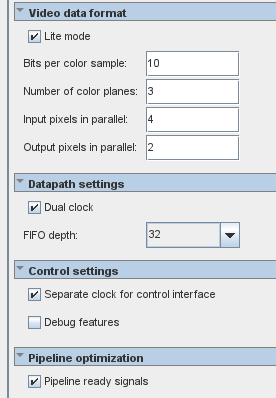
Hello, I am using VVP Pixels In Parallel converter Lite Mode, convert from parallel pixels from 4 to 2. Configurations see below. All the connections are fine and no error messages on Platform Designer. But failed to pass synthesis for errors like, clock connection.. How can I debug this issue? The project is running on Quartus Pro 25.3.0. Thank you.Solved125Views0likes1Comment