Forum Discussion

 New Contributor
Timing violation with Altera GPIO in DDR mode
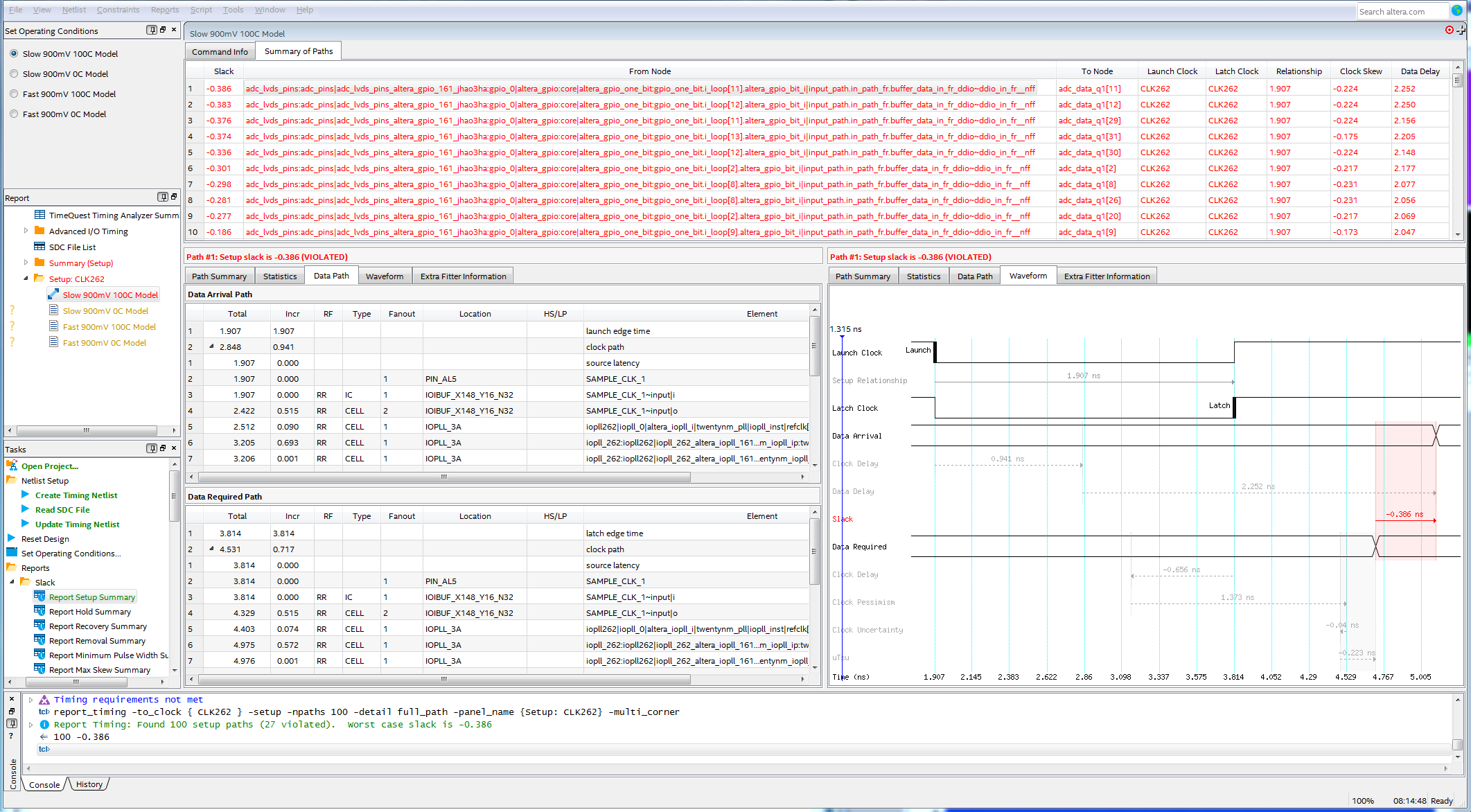
I have a setup violation at the register after the input register. The input register is constrained as described in AN433.
set_input_delay -add_delay -clock virt_adc_clk -min -0.6             [get_ports {ADC_DATA[*]}]
set_input_delay -add_delay -clock virt_adc_clk -min -0.6 -clock_fall [get_ports {ADC_DATA[*]}]

set_input_delay -add_delay -clock virt_adc_clk -max  0.6             [get_ports {ADC_DATA[*]}]
set_input_delay -add_delay -clock virt_adc_clk -max  0.6 -clock_fall [get_ports {ADC_DATA[*]}]

set_false_path -setup -fall_from [get_clocks virt_adc_clk] -rise_to \
[get_clocks CLK262]
set_false_path -setup -rise_from [get_clocks virt_adc_clk] -fall_to \
[get_clocks CLK262]
set_false_path -hold -rise_from [get_clocks virt_adc_clk] -rise_to \
[get_clocks CLK262]
set_false_path -hold -fall_from [get_clocks virt_adc_clk] -fall_to \
[get_clocks CLK262]
But now i have the violation after the input register, as you can see in the picture from Timequest.
Do I miss something?
33 Replies
 KhaiChein_Y_Intel
Regular Contributor
Hi,
I am still looking into this.Please allow me some time on this.
Thanks.
 MRenn
Hi,
thank you for your message.
- KhaiChein_Y_Intel
Hi,
I checked in the Timing Analyzer. The register is located within the I/O. According to the user guide https://www.intel.com/content/dam/www/programmable/us/en/pdfs/literature/ug/ug_altera_gpio.pdf, you may set the delay elements manually in the Intel Quartus Prime settings file (.qsf).
Input Delay Element
set_intance_assignment –to <PIN> -name INPUT_DELAY_CHAIN <0..63>
Output Delay Element set_intance_assignment –to <PIN> -name OUTPUT_DELAY_CHAIN <0..15>
Output Enable Delay Element
set_intance_assignment –to <PIN> -name OE_DELAY_CHAIN <0..15>
You may try to set the max and min value and see if it helps the timing. If no, this is the maximum frequency you can achieve with the I/O standard you have set, 1.8V
Thanks.
- MRenn
Hi,
I tried with Input Delay 0, 1 and 63.
With more delay the setup slack is higher. With Delay set to 1 the hold slack is positive.
I also tried with FAST_INPUT_REGISTER on. No difference.
I never got less than -0.962ns setup slack.
The data delay is 1.341ns. Is the the correct value for a register located within the I/O?
Thanks
- KhaiChein_Y_Intel
Hi,
I am sorry for the late reply as I was out of office for 5 days.
The I/O standard you are using is 1.8V. According to the User guide, https://www.intel.com/content/dam/www/programmable/us/en/pdfs/literature/hb/arria-10/a10_handbook.pdf, user has to use terminated I/O standards if the GPIO is operating at a frequency higher than 250 MHz. SSTL, HSTL, POD and HSUL I/O standards are terminated I/O standards.
Thanks.
- MRenn
H,
I changed the I/O Standard to Differential 1.8V SSTL Class 1, but the negative slack is still there.
In the handbook Intel recommends to use PHYLite for source synchronous Interfaces with more than 200 Mbps.
I tried to set the parameters for this IP.
I set the Interface clock to 262.144MHz, clock rate of user logic: Full
If I do so, I cannot set the PLL reference clock to 262.144MHz. Just half of it, but I need to set this clock, because it is coming from the ADC.
I don't know why it is not possible. In the PHYLite User Guide
https://www.intel.com/content/www/us/en/programmable/documentation/bhc1410942178562.html#bhc1410941851660/en-us Table 3
the Max Core Clock Rate (Full) with Arria 10 Speed Grade -2 is 266MHz.
Do I miss something?
Thanks.
- KhaiChein_Y_Intel
Hi,
To update, I am still looking into this. Please allow me some time on this.
Thanks.
- KhaiChein_Y_Intel
Hi,
I checked with the team, you have to use Phy Lite for frequency above 200 MHz.
Thanks.
- MRenn
Hi,
I tried Phy Lite but had problems with setting the correct frequencies as I wrote 19 days before.
The text was:
In the handbook Intel recommends to use PHYLite for source synchronous Interfaces with more than 200 Mbps.
I set the Interface clock to 262.144MHz, clock rate of user logic: Full
If I do so, I cannot set the PLL reference clock to 262.144MHz. Just half of it, but I need to set this clock, because it is coming from the ADC.
I don't know why it is not possible. In the PHYLite User Guide
https://www.intel.com/content/www/us/en/programmable/documentation/bhc1410942178562.html#bhc1410941851660/en-us Table 3
the Max Core Clock Rate (Full) with Arria 10 Speed Grade -2 is 266MHz.
Thanks.
- KhaiChein_Y_Intel
Hi,
Can you provide the design.qar that is using the PhyLite so that I can look into it?
Thanks.