Forum Discussion

Altera_Forum Honored Contributor
11 years agoHonored ContributorRequest for help in VHDL troubleshooting
Hi all,
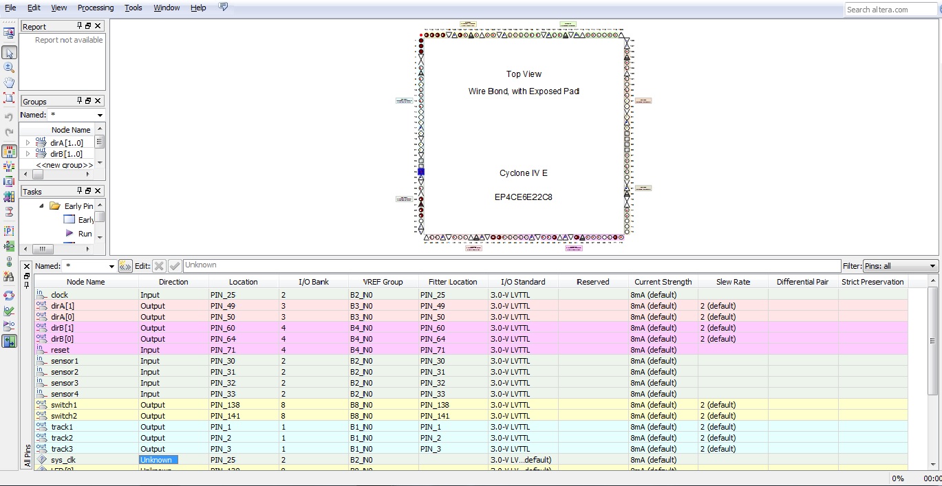
I am a new to programming of VHDL to FPGA. Recently tried experimenting with a code from a book and during simulation, it was functioning perfectly. However after i programmed into Altera Cyclone IV EP4CE chip, the chip is always stuck at the default state regardless of the input. Was suspecting that the clock input is not configured properly thus i assigned the clock to Pin25 and yet it is not helping. Hope anyone can lend a helping hand to help troubleshoot.:(:confused: Thanks alot in advance. The code: LIBRARY IEEE; USE IEEE.STD_LOGIC_1164.ALL; USE IEEE.STD_LOGIC_ARITH.ALL; USE IEEE.STD_LOGIC_UNSIGNED.ALL; ENTITY Traincollision IS PORT( reset, clock, sensor1, sensor2, sensor3, sensor4 : IN STD_LOGIC; switch1, switch2 : OUT STD_LOGIC; track1, track2, track3 : OUT STD_LOGIC; dirA, dirB : OUT STD_LOGIC_VECTOR( 1 DOWNTO 0 )); END Traincollision; ARCHITECTURE a OF Traincollision IS TYPE STATE_TYPE IS ( ABout, Ain, Bin, Astop, Bstop ); SIGNAL state: STATE_TYPE; SIGNAL sensor12, sensor13, sensor24 : STD_LOGIC_VECTOR(1 DOWNTO 0); BEGIN PROCESS ( reset, clock ) BEGIN IF reset = '1' THEN state <= ABout; ELSIF clock'EVENT AND clock = '1' THEN CASE state IS WHEN ABout => CASE Sensor12 IS WHEN "11" => state <= About; WHEN "10"=> state <= Bin; WHEN "01" => state <= Ain; WHEN "00"=> state <= Ain; WHEN OTHERS => state <= ABout; END CASE; WHEN Ain => CASE Sensor24 IS WHEN "11" => state <= Ain; WHEN "10" => state <= ABout; WHEN "01" => state <= Bstop; WHEN "00" => state <= ABout; WHEN OTHERS => state <= ABout; END CASE; WHEN Bin => CASE Sensor13 IS WHEN "11" => state <= Bin; WHEN "10" => state <= ABout; WHEN "01" => state <= Astop; WHEN "00" => state <= About; WHEN OTHERS => state <= ABout; END CASE; WHEN Astop => IF Sensor3 = '0' THEN state <= Ain; ELSE state <= Astop; END IF; WHEN Bstop => IF Sensor4 = '0' THEN state <= Bin; ELSE state <= Bstop; END IF; END CASE; END IF; END PROCESS; sensor12 <= sensor1 & sensor2; sensor13 <= sensor1 & sensor3; sensor24 <= sensor2 & sensor4; Track1 <='0'; WITH state SELECT Track3 <= '1' WHEN ABout, '1' WHEN Ain, '1' WHEN Bin, '1' WHEN Astop, '1' WHEN Bstop; WITH state SELECT Track2 <= '0' WHEN ABout, '0' WHEN Ain, '1' WHEN Bin, '1' WHEN Astop, '0' WHEN Bstop; WITH state SELECT Switch1 <= '0' WHEN ABout, '0' WHEN Ain, '1' WHEN Bin, '1' WHEN Astop, '0' WHEN Bstop; WITH state SELECT Switch2 <= '0' WHEN ABout, '0' WHEN Ain, '1' WHEN Bin, '1' WHEN Astop, '0' WHEN Bstop; WITH state SELECT DirA <= "01" WHEN ABout, "01" WHEN Ain, "01" WHEN Bin, "00" WHEN Astop, "01" WHEN Bstop; WITH state SELECT DirB <= "01" WHEN ABout, "01" WHEN Ain, "01" WHEN Bin, "01" WHEN Astop, "00" WHEN Bstop; END a;20 Replies
 Altera_Forum
Have you written a testbench for this code - have you simulated it>?
- Altera_Forum--- Quote Start --- Have you written a testbench for this code - have you simulated it>? --- Quote End --- Hi Tricky, Thanks for the reply. How do i go about writting a testbench for the code? Read up a few website but still clueless about it.:confused: And website that can help? Greatly appreciate ur help.
- Altera_Forum
There are plenty of tutorial websites. A testbench is some VHDL code that stimulates your design under test. It doesnt have to be synthesisable and you can do plenty of "programming" like things. For example, to generate a clock, you can write:
signal clk : std_logic := '0'; .... clk <= not clk after 5 ns; -- 100 Mhz clock - Altera_Forum--- Quote Start --- There are plenty of tutorial websites. A testbench is some VHDL code that stimulates your design under test. It doesnt have to be synthesisable and you can do plenty of "programming" like things. For example, to generate a clock, you can write:
--- Quote End --- Geezz..Thanks! Having problem understanding the testbench thing. What is the difference between a testbench and simulation with waveform?signal clk : std_logic := '0'; .... clk <= not clk after 5 ns; -- 100 Mhz clock - Altera_Forum
Assuming you're creating a waveform to drive a DUT (design under test), then your waveform IS your testbench.
You run your testbench and DUT in a simulator and you can veiw the waveform in the wave window in the normal way. You need to use a proper simulator (like modelsim) to do HDL simulation. The quartus simulator is not very powerful and only simulates the compiled netlist via waveforms which is very slow compared to simulating the HDL directly. Another advantage of using HDL as the testbench is you can generate far more complex input stimulus, and output practically anything to text files. - Altera_Forum--- Quote Start --- Assuming you're creating a waveform to drive a DUT (design under test), then your waveform IS your testbench. You run your testbench and DUT in a simulator and you can veiw the waveform in the wave window in the normal way. You need to use a proper simulator (like modelsim) to do HDL simulation. The quartus simulator is not very powerful and only simulates the compiled netlist via waveforms which is very slow compared to simulating the HDL directly. Another advantage of using HDL as the testbench is you can generate far more complex input stimulus, and output practically anything to text files. --- Quote End --- Thanks for the explanation. I did the waveform simulation in modelsim then and design work perfectly. However the moment i programmed in and tried out with hardware,it only stay at the default state.:confused: Tried for days troubleshooting but to no avail.
- Altera_Forum
First a small remark
Try to avoid that non standard library as much as possible. There are unfortunately several VHDL books that still use it, but the recommended library for arithmetic is ieee.numeric_std.all. Logic_unsigned will cause you problems the day you will also want to use signed logic in the same architecture, and doesn't live well with numeric_std. Now for you problem I'd definitely check the reset and clock signals first. Are you sure your reset signal is active high? Is your clock on the correct pin? You can use signaltap to record your reset signal, using "clock" as a clock. Then if you don't have a clock you'll get a warning/error from Signaltap, and if you do you will be able to check the polarity of the reset signal. If both look ok then you can begin and checking the other signals from your state machine.USE IEEE.STD_LOGIC_UNSIGNED.ALL; - Altera_Forum--- Quote Start --- First a small remark
Try to avoid that non standard library as much as possible. There are unfortunately several VHDL books that still use it, but the recommended library for arithmetic is ieee.numeric_std.all. Logic_unsigned will cause you problems the day you will also want to use signed logic in the same architecture, and doesn't live well with numeric_std. Now for you problem I'd definitely check the reset and clock signals first. Are you sure your reset signal is active high? Is your clock on the correct pin? You can use signaltap to record your reset signal, using "clock" as a clock. Then if you don't have a clock you'll get a warning/error from Signaltap, and if you do you will be able to check the polarity of the reset signal. If both look ok then you can begin and checking the other signals from your state machine. --- Quote End --- Hi daixiwen, Thanks for introducing the signaltap function to me.. Both u n tricky are a great help,learnt something from u guys!USE IEEE.STD_LOGIC_UNSIGNED.ALL; - Altera_Forum
Hi Tricky and Daixiwen,
I have tried both the waveform simulation and the signaltap. Noticed that the default state is 'ABout' and it is alway in default state even though i tried triggering the sensor 1 and sensor 2. Rightfully when sensor 1 is a high then the state should have switch from ABout to Ain. Yet both ABout and Ain are activated. In this case, what will be the state that the chip is in?:confused: - Altera_Forum
Your diagram shows that the reset signal is constant '1' - why?