Forum Discussion

 New Contributor
MAX10M04 / Quartus Prime Lite Edition
Good morning,
I'm completing a project with MAX10M04 FPGA and Quartus Prime 20.1 Lite Edition software.
The project is in the final phase, everything works fine but I have a very strange problem: I used the schematic for the whole FPGA project and using the same component I built "1Encoder" four times it gives me problems just by connecting the hardware of the 4th component.
Not connecting this all the whole project works perfectly.
Are there any limitations using the "Lite Edition"?
I attach the FPGA project and the wiring diagram of my board.
Thanks.
28 Replies
 Gigiz
GigizHello Nurina,
I want to inform you that I have solved the problem, thanks.
Best regards,
Gigi
 Nurina
Regular Contributor
Hi Gigi,
I suggest you open a new case if you come across a problem in the future so that it will be easier for the community to navigate in case they come across the same problem as you are now dealing with a different tool on Quartus.
Regards,
Nurina
- Gigiz
Hello Nurina,
I have not solve the problem yet.
Regards,
Gigi
- Nurina
Hi Gigi,
Sorry for coming back to you so late.
You can perform this on the Lite version. You first need to specify your EDA tool.
Go to Assignments->Settings->EDA Tool Settings then set to ModelSim or ModelSim-Altera
Then under Tools->Options->General->EDA Tool Options set the path of the tool you chose to "C:/intelFPGA_lite/20.1/modelsim_ase/win32aloem"
You can also try SignalTap, this would allow you to spot check a couple I/O signals and observe the signals.
Regards,
Nurina
- Nurina
Hi Gigi,
We did not receive any response to the previous question/reply/answer that I have provided, thus I will put this case to close pending. Please post a response in the next 15 days to allow me to continue to support you. After 15 days, this thread will be transitioned to community support. The community users will be able to help you with your follow-up questions.
Regards,
Nurina
PS: If you find any comment from the community or Intel Support to be helpful, feel free to give Kudos.
- Nurina
Hi Gigi,
It's best to investigate this problem with an RTL simulation. These signals might be affected by other signals or the clock hence behaving unexpectedly.
I know it'll take some time to do that so you can just come back here for consultation on that whenever you're ready.
Best regards,
Nurina
- Gigiz
Hi Nurina,
How can I start RTL simulation ?
In Tools- Run Simulation tool - RTL simulation
I have the message: You did not specify EDA simulation tool.
Is possible to do it with Quartus Prime Lite Edition ?
Quartus Prime Lite Edition has expired time functionality and support ?
If so, how is possible expand this time ?
Can I continue to use Quartus Prime Lite Edition without buy standard/pro version ?
Thanks.
Best Regards,
Gigi
- Nurina
Hi Gigi,
My previous reply suggests you to solve the timing warnings by constraining the clock signals using Timing Analyzer.
So you're trying to figure out why that happens? By solved do you mean that all 4 counters work together as expected?
Regards,
Nurina
- Gigiz
Hi Nurina,
I'm trying to understand the problem...
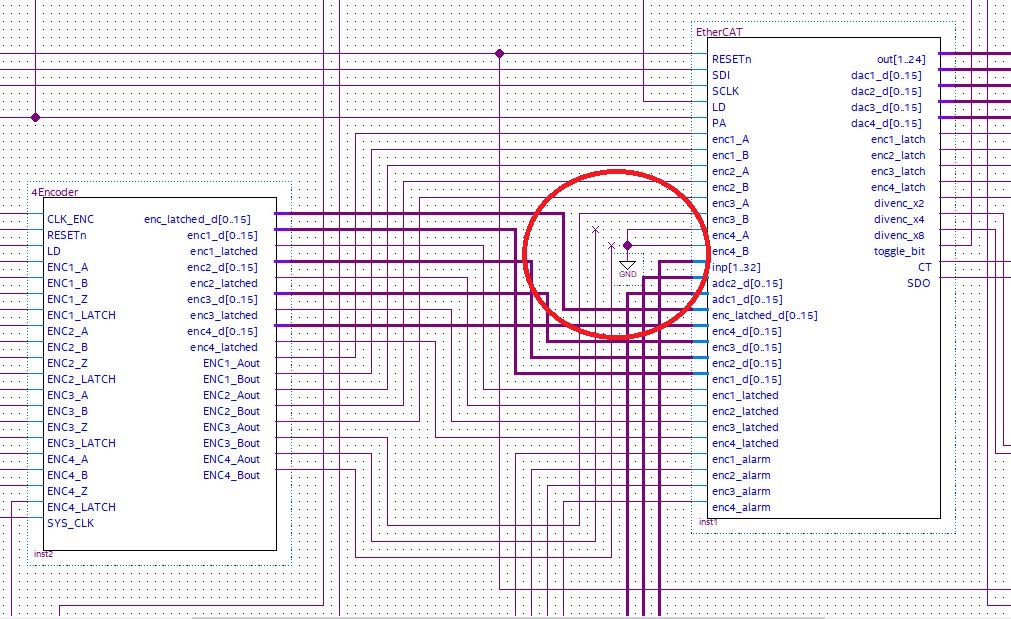
Yes connecting directly to ground this two signals all 4 encoders running properly, all board running without problems.
These 2 signals are only for monitor and have not particular functionality on the board.
Best regards,
Gigi
- Nurina
Hi Gigi,
We did not receive any response to the previous answer that I have provided, thus I will put this case to close pending. Please post a response in the next 15 days to allow me to continue to support you. After 15 days, this thread will be transitioned to community support. The community users will be able to help you with your follow-up questions.
Regards,
Nurina
PS: If you find any comment from the community or Intel Support to be helpful, feel free to give Kudos.- Gigiz
- Nurina
Hi Gigi,
You can fix those warnings by constraining the clock signals using Timing Analyzer. Go to Tools->Timing Analyzer.
Here is a reference on it: https://www.intel.com/content/dam/www/programmable/us/en/pdfs/literature/manual/mnl_timequest_cookbook.pdf
Regards,
Nurina
- Nurina
Hi Gigi,
I don't see signals "ENC4_A" and "ENC4_B" connected to the ground in your new design file. Can you explain what those signals, along with the alarm signal do?
Can you use the SignalTap logic analyzer on the 4Encoder to probe and debug the behaviour of internal signals during normal device operation? SignalTap can be used to monitor your real time signal, so you can find the root cause of the problem.
Here's a document that can help you understand SignalTap: https://www.intel.com/content/dam/www/programmable/us/en/pdfs/literature/hb/qts/qts_qii53009.pdf?wapkw=signal%20tap%20
There are also some training courses about SignalTap available on Intel FPGA's YouTube channel: https://www.youtube.com/watch?v=RtPqQ25hSIk
Regards,
Nurina
- Nurina
Hi Gigi,
Yes, I did. You can ignore most of them, but I suggest you do something about the multiple warnings about overlapping block or symbols. Follow the solution available here: https://www.intel.com/content/www/us/en/programmable/quartushelp/13.0/mergedProjects/msgs/msgs/egdfx_symbols_overlap_error.htm
Also, I've checked your pin planner and it seems that you are using a clock pin for the EXT_ENC4_ALARM node, I think that's the cause of the problem. Use a differential pin for this node like you did with the other ALARM nodes.
Regards,
Nurina
- Gigiz
Hi Nurina,
I have fixed all overlap blocks warnings ID 275059.
I have many warnings ID 332060 and one ID 332068 (no clocks defined in design),
how can I fix them ?
Thanks.
Best Regards,
Gigi
- Gigiz
Hi Nurina,
the hardware circuit is just connected to EXT_ENC4_ALARM and it is configured as standard input (I think).
I use other signals connected to others clock pin without problem.
The external clock is on pin 27.
I have also many warnings #332060, How I can configure the CLOCK input and associated it to the other signals ?
Gigi