ethernet
164 Topics
Evaluation license for 10Gbps Ethernet MAC
Hello, Any help will be much appreciated - I would like to evaluate the 'Low Latency 10Gbps Ethernet MAC (6AF7 0119)', but I can not find the appropriate evaluation license on the self-service-licensing center. Even though 'Intel FPGA IP Evaluation Mode' is enabled I keep getting the 'you do not have a valid license' message in the assembler stage (Quartus Prime Version 25.1.0, the device is an Agilex5). Thank you!39Views0likes3Comments
Introducing the Altera Community AI Responder — Beta
Altera is introducing the AI Responder, an assistant built into the Altera Community to help provide faster, context-aware guidance for Altera product questions. It uses relevant public Altera documentation and Knowledge Database content, with coverage continuing to expand. The AI Responder may provide source references and can hand off complex or out-of-scope questions to an Altera subject-matter expert. As a beta feature, responses may contain errors or omissions, so please review the sources and verify technical guidance against official Altera documentation before implementation. If the response does not fully address your question, add more context and tag ai_responder to continue the discussion. We welcome your feedback as we improve the Community experience.22Views0likes0Comments
F-tile 10GE Ethernet Reference Design ISSP Error
Hello, I am currently a master's student and apart of the research I am working on at my lab involves implementing a subsection of the O-RAN 5G fronthaul interface on an Agilex 7 FPGA, which will depends on the F-Tile Ethernet Hard IP. I have been working with the 10GE F-Tile Ethernet Hard IP reference design and have successfully compiled the design, programmed the generated image onto the FPGA, and accessed the provided test utilities through Quartus System Console. However, I am encountering issues when running the serial loopback test. On the initial attempts, the test runs but reports packet mismatches and ultimately fails. On subsequent attempts, I receive errors indicating a value mismatch involving an ISSP probe. I would appreciate additional guidance on troubleshooting the ISSP probe mismatch. I have also observed that rx_pcs_ready does not assert during testing, which appears to indicate an issue with the RX path. I am unsure whether this is directly related to the ISSP probe issue or represents an additional problem with the RX configuration or link initialization. Could you provide guidance on how to diagnose and resolve the ISSP probe value mismatch, as well as what conditions are required for rx_pcs_ready to assert in the 10GE F-Tile reference design? Specifications: - Quartus Prime Pro 24.1 - jtagd 24.1 executable was replaced with jtagd 25.1 version to allow USB Blaster III support (The specific board I am using mentions to do this in their BSP) - Device model: AGFB027R24C2E2V % run_test --- Turning off packet generation ---- -------- Printing PHY status --------- ------------------------------------ -------------------------------------- -------- Enabling loopback ---------- -------------------------------------- Applying Rx Reset Reading Loop Back Register Status reg1_xcvr0 0x00062340 reg2_xcvr0 0x00062340 Loop Back for Lane 3 .. Writing 1st loopback data for Lane 3 Reading Loop Back Registers reg1_xcvr0 lane 3 0x0006a340 reg2_xcvr0 lane 3 0x0006a340 Writing 2nd loopback data for Lane 3 Reading Loop Back Registers reg1_xcvr0 lane 3 0x00062340 reg2_xcvr0 lane 3 0x00062340 Releasing Rx Reset Checking Status of the Flux Register lane 0 0x00000000 lane 1 0x00000000 lane 2 0x00000000 lane 3 0x00000000 --- Wait for RX clock to settle... --- -------------------------------------- RX PHY Register Access: Checking Clock Frequencies (KHz) TXCLK :402840 (KHZ) RXCLK :161130 (KHZ) TX PLL Lock Status 0x00000001 Rx Frequency Lock Status 0x00000000 RX PCS Ready 0x0 TX Lanes Stable 0x1 Deskewed Status 0x0 Link Fault Status 0x00000001 Rx Frame Error 0xdeadc0de Rx AM LOCK Condition 0xdeadc0de Value from issp reset probe is 0xed/0b11101101 ERROR:rx_pcs_ready is not asserted or link fault is detected. Expected value from issp reset probe is : 0xff ---------------- Done ---------------- Thank you for any guidance you can provideSolved93Views0likes4Comments
Agilex 5 GTS Supported Protocols
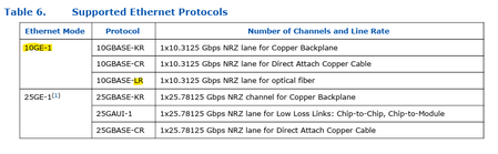
Hi Altera/Community, I’m trying to better understand the protocols supported by the Agilex 5 GTS transceivers. In the user guide, it mentions that the supported protocol is 10GBase-LR. I wanted to confirm: is 10GBase-R the underlying protocol used before the optical module? Also, does this mean that other optical modules, such as 10GBase-SR, are supported as well? Any clarification on how the transceivers interact with different optical modules would be greatly appreciated. Thanks in advance!209Views0likes6Comments
Agilex 5 Reset Sequencer - Design Assitant reports IPC-40038 violation
Hi, I am using 2x25Gbit PCS/PMA function only (with FEC) and 2x10Gbit PCS/PMA function only (without FEC) in my Agilex 5 design (device A5ED043AB32AE3V, Quartus Pro 26.1). 25Gbit transceiver are using IO bank 4C while 10Gbit transceivers are using IO bank 1C There is one reference clock driving the GTS PLL as well as the PMA reference clock input of the Ethernet IP core for both the 25Gbit interface and the 10Gbit interface. They are located in the IO bank of their transceivers. There is one Reset Sequencer for 25Gbit and 10Gbit each. Quartus compiles the design without errors but the Design Assitant reports a Critical Error "IPC-40038 - Individual bit of Control Unit clock of Reset Sequencer IP can drive only a single instance of Ethernet or PCIE IP" Basically I followed the Use Case 1 chapter 5.6.1 of the GTS Transceiver PHY User Guide version 2026.03.13. Both PCS/PMA units of each type receive the same o_pma_cu_clk from their Reset Sequencer. In a Quad there is just one or two Ethernet Hard IPs but there are 4 PCS/PMA functions accordig to the same document. Can I safely ignore this Critical Warning, is the Warning wrong or do I miss something? Thank you GerhardSolved184Views1like10CommentsRX Mac segmented interface detailed information
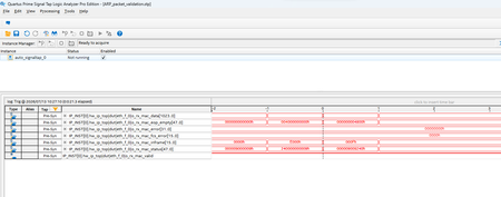
I am using Ftile ethernet hard IP (400G configuration) . I complied the example test design with signal tap to monitor RX mac segmented interface and loaded on MA2700 . The kit is connected to a host with 400G capable NIC in it. I am using ping command and via wireshark I can see that host sends ARP request packet to the kit. As the ARP request packets are sent to the kit, I triggered STP and capture I have attached screenshot. you can see all data in the capture other than rx_mac data. rx mac data on clock -1 and 0 are as following -1 -> E39001000406000801000608AAEB6A17E390FFFFFFFFFFFFD5555555555555FB070707070707070707070707070707070707070707070707070707070707070707070707070707070707070707070707070707070707070707070707070707070707070707070707070707070707070707070707070707070707070707070707 0 -> 070707070707070707070707070707070707070707070707070707070707070707070707070707070707070707070707070707070707070707070707070707070707070707070707070707070707070707070707070707FDE831AB370000000000000000000000000000000000006501A8C0000000000000C801A8C0AAEB6A17 From wireshark I can see this ARP packet is 60bytes and all the fields matches with what I see in the o_rx_mac_data. Now I am trying to make sense of Rx mac segmented interface and I have following questions. rx mac inframe values are E000h and 000Fh meaning total 7 bits are 1 (logic high) indicating 56 byte packet but from payload is 60 bytes. So how do I equate for remining 4 bytes? in user guide o_rx_mac_eop_empty [47:0] signal is explained as "Indicates the number of empty bytes on the RX data signal, starting from the most significant byte (MSB). Valid only on EOP segments." I dont understand this statement completely so please help; as per signal tap waveform clock 0 is where packet ends and the value of bus is 4800h. I am not sure if and how this value can help equates for missing 4 bytes. Figure 44. Receiving Data Using the RX MAC Client Interface is little help- and small explanation below it (has typos i think) is not much help. Do you have more details and example for MAC segmented interface which you can share with me so that I can learn exact details on how to use this interface to receive incoming packets from Ftile. Using above signaltap screenshot and o_rx_mac_data values for clock -1 and 0; how do i detect sop? how do i use rx mac_sengemented interface to detect eop ? how do i use rx mac_sengemented interface detect exact length of ethernet frame which is being supplied during clock -1 and 0.91Views0likes4CommentsTriple-Speed Ethernet IP for Agilex 5 fails during Quartus Synthesis
Hi, I am using the IP core version 12.0.0. of the Triple-Speed Ethernet IP in the configuration PCS only with LVDS "transceivers" & HPS adapter. The target FPGA is an Agilex 5 namely the A5ED043AB32AE3V. The IP core issues an error during Analysis & Synthesis in Quartus Pro 2026.1. Error(18842): The ENABLE port on clock gate i_altera_pcs_pma_1g_hps|eth_tse_0|hps_gmii_adapter_instance|u_pcs_rx_clk_gated|altclkctrl_comp|altclkctrl_inst|clkena_inst is connected to a constant. It must be driven by a real signal. I checked the generated netlists. The error occurs in an encrypted section; thus I can not change anything. The usage of the IP core is straight forward. Connect to the Platform Designer project of the HPS, where I fed out EMAC0. There is nothing I can change during generation of the IP core nor its instantiation. For me this looks like (another) Agilex 5 bug. Regards Gerhard101Views0likes4CommentsF-tile ethernet hard ip in agilex7
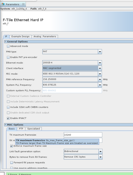
I generate 200G ethernet F-tile hard ip that base on agilex7, the IP configuration as follow: Our current test setup uses our custom development boards interconnected with Mellanox CX-8. The link fails to come up regardless of whether the CX-8 is configured in forced mode or auto-negotiation mode. Could you advise on how I should troubleshoot this issue next? Additionally, I would like to ask: Does the F-Tile Ethernet Hard IP support filtering packets smaller than 64 bytes? I cannot find the corresponding configuration options in the IP configuration GUI.Solved118Views0likes5Comments