Forum Discussion

Altera_Forum Honored Contributor
17 years agoHonored ContributorClocked Video Output slave control not functioning
I have not successfully gotten Clocked Video Output to take dynamic configuration from it's slave port. I can use the wizard to configure it, but none of the 1-14 video modes will configure.
Yes, I set them invalid before changing the settings and then make them valid. However, according to the current mode register, it stays stuck at mode 0.35 Replies
 Altera_Forum
I could find the problem. I have had huge ringing on the databus. Reducing drive streng and put some resistors fixed the problem.
Thank your for your attention, guys!- Altera_Forum
Hello,
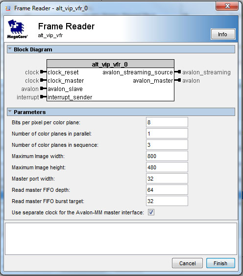
I'm sorry to put the subject up again, but I'm having a lot of trouble with the CVO configuration. And because here is a lot of info about this part I posted here... I'm working together with Peet_2 on this forum to get our design working. we're working on the Cyclone III Nios II evaluation kit (NEEK) and we're trying to implement a Frame reader and a VCO to display data from RAM onto the display (see SOPC image included). But strange things happen. We tried several setups, but our goal was never achieved... -First we tried using the test pattern generator combined with the VCO. Which worked perfectly. -We added a frame reader and used the Video_synced_out with a couple of bridges. It flickered (Avalon ST vs Video pipeline conflict), but we saw our red image (see code in attachment), which prooved the Frame reader was working properly. -When we connect the CVO to the FR, we got no image. Here VCO uses no control port. -So I activated the control port option of the VCO (because you see it's activated in every example I found on the VIP) and tried to set it up, but still no image. The code we used to activate the CVO and FR is included here. If there's anyone around here who could give us some help, it would really be appreciated. We're working on this problem for several weeks now, and some help would be really welcome. You can follow our current progression, and download the complete designs on the following thread: http://www.alteraforum.com/forum/showthread.php?p=90220#post90220 Thanks in advance, Hans and Peet_2 - Altera_Forum--- Quote Start --- Hello, -First we tried using the test pattern generator combined with the VCO. Which worked perfectly. --- Quote End --- Hi, if the TPG to CVO (no control port) design is working then my recommendation would be to stick with that CVO, there is no need to enable the control port. Changing multiple things at once will make the design more difficult to debug. The problem is most likely with the configuration of the Frame Reader. Can you post a screenshot of the Frame Reader GUI so that I can take a look? Regards, Gareth.
- Altera_Forum
Hi and thanks for your reply, I attached a screenshot to this post.
@Hans: I think there is one value wrong in your configuration: IOWR(ALT_VIP_ITC_0_BASE, 11 ,261); // HORIZONTAL BLANK in my calculation Horizontal Blank must be frontporch+syncpulse+backporch = 40+1+216 = 257. Can you tell me, why you used 216? Thanks.My Configuration is: IOWR(ALT_VIP_VFR_0_BASE, 3, 0); // Frame Select IOWR(ALT_VIP_VFR_0_BASE, 4, DDR_SDRAM_BASE); // Frame 0 Base Address IOWR(ALT_VIP_VFR_0_BASE, 5, 384000); // Frame 0 Words IOWR(ALT_VIP_VFR_0_BASE, 6, 384000); // Frame 0 Single Cycle Color Patterns IOWR(ALT_VIP_VFR_0_BASE, 7, 0); // Frame 0 Reserved Bit IOWR(ALT_VIP_VFR_0_BASE, 8, 800); // Frame 0 Width IOWR(ALT_VIP_VFR_0_BASE, 9, 480); // Frame 0 Height IOWR(ALT_VIP_VFR_0_BASE, 10, 3); // Frame 0 Interlaced IOWR(ALT_VIP_VFR_0_BASE, 0, 1); // start Frame Reader - Altera_Forum
- Altera_Forum
Seems Peet was one minute faster then I was. :rolleyes:
--- Quote Start --- @Hans: I think there is one value wrong in your configuration: IOWR(ALT_VIP_ITC_0_BASE, 11 ,261); // HORIZONTAL BLANK in my calculation Horizontal Blank must be frontporch+syncpulse+backporch = 40+1+216 = 257. Can you tell me, why you used 216? --- Quote End --- I used a 5 as syncpulse, I was sure this worked in my previous experiments, therefore I came to 261 (40+5+216). @Peet: It seems we have different settings for read master FIFO depth. I don't know if it can cause problems when the FIFO is too big/too small. Best Hans - Altera_Forum
I have seen, that we have different settings, too. Perhaps Gareth can give us a hint. ;-)
- Altera_Forum--- Quote Start --- @Peet: It seems we have different settings for read master FIFO depth. I don't know if it can cause problems when the FIFO is too big/too small. --- Quote End --- Setting the FIFO depth to twice that of the burst size should be sufficient for most cases. That would be 64 in this case. Your Frame Reader configurations looks fine. One possible problem is that the data rate coming from the Frame Reader may not be sufficient to supply the output video rate. Using signal tap you can check the rate of data coming out of the Frame Reader by tapping the dout port. Inside the CVO there is a signal called sync_lost, if this is continually firing the CVO isn't receiving data fast enough and is having to reset the video output. Regards, Gareth.
- Altera_Forum
Hello,
@Gareth Duncan: You cave me somekind of hint when you said there was a lost_sync problem. Indeed there is, the 3th bit of the status Register (VCO) is constantly giving a five as output, which means the buffer is underflowing (I think). I already changed the "start FIFO output" of the VCO to about 2/3ths (600/800) of the original FIFO size, instead of 0, which didn't change a thing yet. I also have some good news, I found in my collection of examples an example design for the NEEK(!) which uses (almost) every feature of the VIP suite. I cannot upload it immediatly for you because the zip file is about 125 MB (I will put it on rapidshare as fast as I can, so you can all download it and experiment with it). The name of the design is NEEK_VIP_demo_LCD_SVGA_v91_r1_src, I don't find the original zip file back and I don't know where I downloaded it (it must be a long time ago) @Peet: I already added the SOPC file to the post here and as you can see, they also use the frame buffer between the alpha blender and the VCO. May be this is necessairy to output a nice stream of data. (just a thought) A second thought goes to the use of his own verilog programmed "serializer" for the video output streams. All the components in the SOPC use a 3 pixel in parallel transmission (which is not good for the NEEK VGA and LCD) and after the VCO he added some verliog code to serialize those three pixel data blocks for transmission to the MAX II on the LCD board. Could there be a problem with the serial data stream we used? I have to run now, I'm sorry I cannot upload the example immediately, I will do it as fast as I can, because I think you'll all be interested! But I think for now there is some light at the end of the tunnel! I will start this example design from scratch and study every possibility next week to understand the real flow of the VIP. Have a nice weekend! Best, Hans - Altera_Forum--- Quote Start --- Indeed there is, the 3th bit of the status Register (VCO) is constantly giving a five as output, which means the buffer is underflowing (I think). --- Quote End --- One thing to note is that the underflow bit of the status register is sticky. Once fired it will stay high until you clear it by writing a 1 to that bit. So to check for underflow you should poll the register every so often, clearing it after you've read it. --- Quote Start --- they also use the frame buffer between the alpha blender and the VCO. May be this is necessairy to output a nice stream of data. (just a thought) --- Quote End --- A Frame Buffer won't help in this case as the Frame Reader is effectively the read half of a Frame Buffer (it has the same functionality and is able to repeat output frames). If the output is underflowing then the likely issue is that the Frame Reader isn't getting enough bandwidth from the memory interface. This could be because some other component is accessing the memory inefficiently e.g. a NIOS doing single random access reads and writes. Try running the NIOS from on-chip RAM or SSRAM to eliminate this cause. Also the clock crossing bridge isn't necessary for the Frame Reader and may not be working efficiently. Remove it and change the clock on the Frame Reader's Avalon Master interface to be the ddr_sdram clock. --- Quote Start --- All the components in the SOPC use a 3 pixel in parallel transmission (which is not good for the NEEK VGA and LCD) and after the VCO he added some verliog code to serialize those three pixel data blocks for transmission to the MAX II on the LCD board. --- Quote End --- You could also use the Color Plane Sequencer VIP core to do this. It allows you to convert between colors in parallel and colors in sequence. Gareth.