Forum Discussion

 Honored Contributor
Driving Ladder DAC
Hi,
Im trying to drive a resistor ladder DAC from my DE-1 SOC board, despite of my DAC being very accurate im getting somewhat shotty results. The setup is relatively simple driving the resistors directly from the board. Right now im using plain old 3.3v ttl to drive it. I was wondering what output standard is best used, and if I can drive Z to it without any troubles? Kind Regards, Camper.12 Replies
 Altera_Forum
Driving 'Z' shouldn't be an issue.
As for the I/O standard - that depends on your design. 3.3V (or 3.0V, 2.5 etc.) TTL or CMOS sounds fine to me and would be what I'd assume to use. Cheers, Alex- Altera_Forum
Awesome! Ill post some images when I get back at it :)
- Altera_Forum
Upon closer inspection I must have botched something using a case statement to drive my logic. So things might not be so gruesome as they appear in the 1st picture :P
EDIT: Nope, its bad, "this" bad then. https://alteraforum.com/forum/attachment.php?attachmentid=15341&stc=1 Im scratching my head as to what can be causing this issue, does this mean the current gets sunk into ground and only the spikes shows up on the image? Should it? Should I be wanting a higher impedance from it? - Altera_Forum
I was hoping to have it right this time, but no luck so far same output from this.
assign GPIO_1[35] = signal[11] ? 1'b1 : 1'bZ; My question was does this perform the trick of setting the pin to Z directly? - Altera_Forum
What should the waveform look like?
Do you have passive pullups and/or bus hold function enabled on those I/Os? Can you set all the outputs to Z, and then only drive one bit (ie, the msb) between Z and 1 (or Z and 0) and capture the waveform? - Altera_Forum
It shoud look like the 3rd picture in the first series, A somewhat shotty sawtooth wave.
I cant do much "Warning (169133): Can't reserve pin GPIO_0[15] -- pin name is an illegal or unsupported format" So it's the standard setting, it might have an internal pullup enabled. Given the on off hobbyist experience, I don't know much about the board configuration, other than its a bidirectional ttl pin. https://alteraforum.com/forum/attachment.php?attachmentid=15352&stc=1 I put all the lines to Z, it did show a decent square wave. https://alteraforum.com/forum/attachment.php?attachmentid=15353&stc=1 When I run the previous arrangement it shows a good squarewave as well. The problem arises when I connect extra lines to it. It instantly sags to a seemingly nominal level. - Altera_Forum
It would be interesting to see one line at a time toggle between 0 and Z, or 1 and Z, with all other lines at Z.
You should get reasonably good looking square waves at different frequencies, correct? What are the values of the resistors in the ladder? If they are too low, will draw too much current, if too high than leakage from pin will change effective value. - Altera_Forum
The first image is what I would expect to see; each bar is about twice the height of the previous bar.
The other two images appear to have an added bias (ie, base value) compared to the first image. If as you say the resistor values are 300-600-1200-2400-4800-9600-19200-38400-76800 (like the baud rates...) then if the passive pullup were enabled, typically about 25K, it would really start to affect the values above 9600 rather dramatically, enabling a 25K pullup to H, when your resistor is pulling to L, forming a voltage divider. Just my suspicion based on your waveforms. - Altera_Forum
I found the menu responsible for this in the pin planner. According to "this page" (https://www.altera.com/support/support-resources/knowledge-base/solutions/rd01112011_164.html) there is no way around this. Also there is nothing useful in the "pin connection guidelines" for cyclone5 devices..
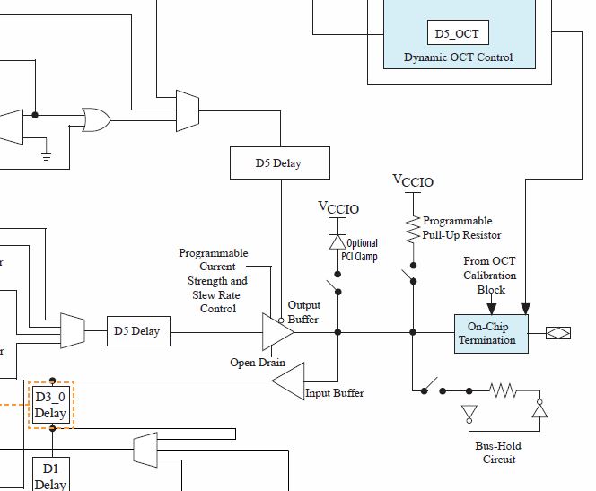
So is there a way to remedy this? - Altera_Forum--- Quote Start --- I found the menu responsible for this in the pin planner. According to "this page" (https://www.altera.com/support/support-resources/knowledge-base/solutions/rd01112011_164.html) there is no way around this. Also there is nothing useful in the "pin connection guidelines" for cyclone5 devices.. So is there a way to remedy this? --- Quote End --- That indicates that before a device is configured, and during configuration, the weak pullups will be enabled on the I/O pins. However, you can configure the I/Os to have no weak pullup and no bus hold, so a output that is disabled will only source the leakage current (between -30uA and +30uA per datasheet). BTW 30uA at 3.3V is about 110K effective ohms (minimum; will be higher for lower currents) so even with the weak pullup disabled there will be a pullup/pulldown of something on the order of 110K to 220K or so ohms per I/O. Picture of the I/O structure:https://alteraforum.com/forum/attachment.php?attachmentid=15362&stc=1