Forum Discussion

 Honored Contributor
Implementation of Digital PID controller in FPGA
I'm trying to implement a PI controller in FPGA using schematic entry method in altera quartus II . I'm using the following equivalent PI controller equation,
c(n) = c(n-1)+kp*(e(n)-e(n-1))+Ki*T*e(n-1) where, c(n) = controller output Kp= proportional constant Ki=integral constant e(n)=Reference -actual input T=sampling period I'm implementing it for 8 bit data. I couldnot implement c(n-1) in the above equation using schematic entry. Can someone help me implement this? I would be grateful if you can suggest me other ways of implementing PI controller like in VHDL.30 Replies
 Altera_Forum
Looks like you will need a storage element. Perhaps a fifo would work or a D-flipflop with an enable.
- Altera_Forum
gmpstr,
Thanks a lot for response. I used D type flip flop and I sucessfully implemented kp*(e(n)-e(n-1))+Ki*T*e(n-1) but once I took the c(n) and pass it through D type flip flop to get c(n-1) and add to above, my problem started. The value of c(n-1) is always zero though it acutally is not and the result is just always equal to kp*(e(n)-e(n-1))+Ki*T*e(n-1). During synthesis, I got the following warning, Warning (14130): Reduced register "lpm_dff0:inst9|lpm_ff:lpm_ff_component|dffs[0]" with stuck data_in port to stuck value GND Warning: Output pins are stuck at VCC or GND Warning (13410): Pin "output[0]" is stuck at GND Maybe this will help you understand my problem. I hope to get feedback from you in this matter. - Altera_Forum
You need to figure out why the data_in port is being reported as stuck at GND. You could post a quartus archive of the design and I'm sure you would get feedback that would solve the issue.
- Altera_Forum--- Quote Start --- I'm trying to implement a PI controller in FPGA using schematic entry method in altera quartus II . I'm using the following equivalent PI controller equation, c(n) = c(n-1)+kp*(e(n)-e(n-1))+Ki*T*e(n-1) where, c(n) = controller output Kp= proportional constant Ki=integral constant e(n)=Reference -actual input T=sampling period I'm implementing it for 8 bit data. I couldnot implement c(n-1) in the above equation using schematic entry. Can someone help me implement this? I would be grateful if you can suggest me other ways of implementing PI controller like in VHDL. --- Quote End --- Hi, can you post your schematic ? If you don't what to use VHDL , maybe Verilog could be a choice ? Kind regards GPK
- Altera_Forum
Some years ago, I started programming DSP applications with maxplus2 and schematic entry.You can achieve any kind of arithmetic utilizing the respective MegaFunctions. However, you have to assure, that c(n) sum doesn't overflow. Standard add and sub operators or megafunctions don't provide saturation logic, you have to add it separately.
- Altera_Forum
Hi everyone,
I've attached the archive of PI controller project. I've used altera megafunctions in this schematic entry. Pls help me solve this problem. I've not yet added saturation logic on it. - Altera_Forum
Warning (14130): Reduced register "lpm_dff0:inst9|lpm_ff:lpm_ff_component|dffs[0]" with stuck data_in port to stuck value GND
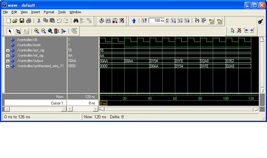
Warning: Output pins are stuck at VCC or GND Warning (13410): Pin "output[0]" is stuck at GND These warnings make sense after looking at the schematic. The two multipliers before the add are doing a multiply by 2 so the result will always be even, thus bit 0 will always be 0. Also noticed that The two dff on the top left(inst1 and inst2) are 16 bit but should be 8bit. When I double click them, the megawizard shows them as 16 bit. Not sure if this is a problem. I fixed that issue and ran a modelsim simulation and the simulation shows data coming out of the dff of inst9. synthesized_wire_11 is the output of dff(inst9) - Altera_Forum
gmpstr,
I looked on the simulated output of yours and it seems to work fine, But when I tried to simulate the schematic with the corrections you mentioned with a waveform file, I got correct result for 2 periods only. I've attached .vwf file . Could you pls tell me what went wrong? - Altera_Forum--- Quote Start --- Also noticed that The two dff on the top left(inst1 and inst2) are 16 bit but should be 8bit. When I double click them, the megawizard shows them as 16 bit. Not sure if this is a problem. --- Quote End --- The width is automaticly set to 8 in compilation, even without causing a warning. This is a special feature of schematic entry evaluation, I think. It also infers a multi-bit register from a single bit one. --- Quote Start --- But when I tried to simulate the schematic with the corrections you mentioned with a waveform file, I got correct result for 2 periods only. --- Quote End --- I see, that your simulation output has 8 bit. I don't understand what you connected here, cause your design has a 16-bit output. Generally I see two problems. Controller deviation signal e is by it's nature of SIGNED type, no matter what your input signals are. To my opinion it's advisable, to use SIGNED for all signals throughout a PI controller, also for coefficients to avoid type confusion. The output stuck to ground refers to a problem of coefficient scaling and required signal widths in your design. I already mentioned the need to limit the integrator output. These points are not related to FPGA programming rather than basic DSP issues. They also arise with digital microprocessor controllers and can be examined (and solved) by pencil and paper methods. P.S.: As another supplement: Cause the sampling period T most likely is a multiple of the system clock period, the delaying FFs should have a clock enable to set the sampling period.
- Altera_Forum
Hi everyone. I'm also triyng to implement a PID in quartus schematic. Does anyone knows ho to make a correct saturation for adders? i've thinked about use multiplexer with index bit carry and bit overflow.
thank you for your help