Forum Discussion
 Occasional Contributor
F-tile transceiver IP simulation
Hello Intel FPGA forum,
I am attempting to simulate the F-tile Architecture and PMA and FEC Direct PHY IP core. I have generated RX and TX simplex IPs, as well as the F-Tile Reference and System PLL Clocks Intel FPGA IP.
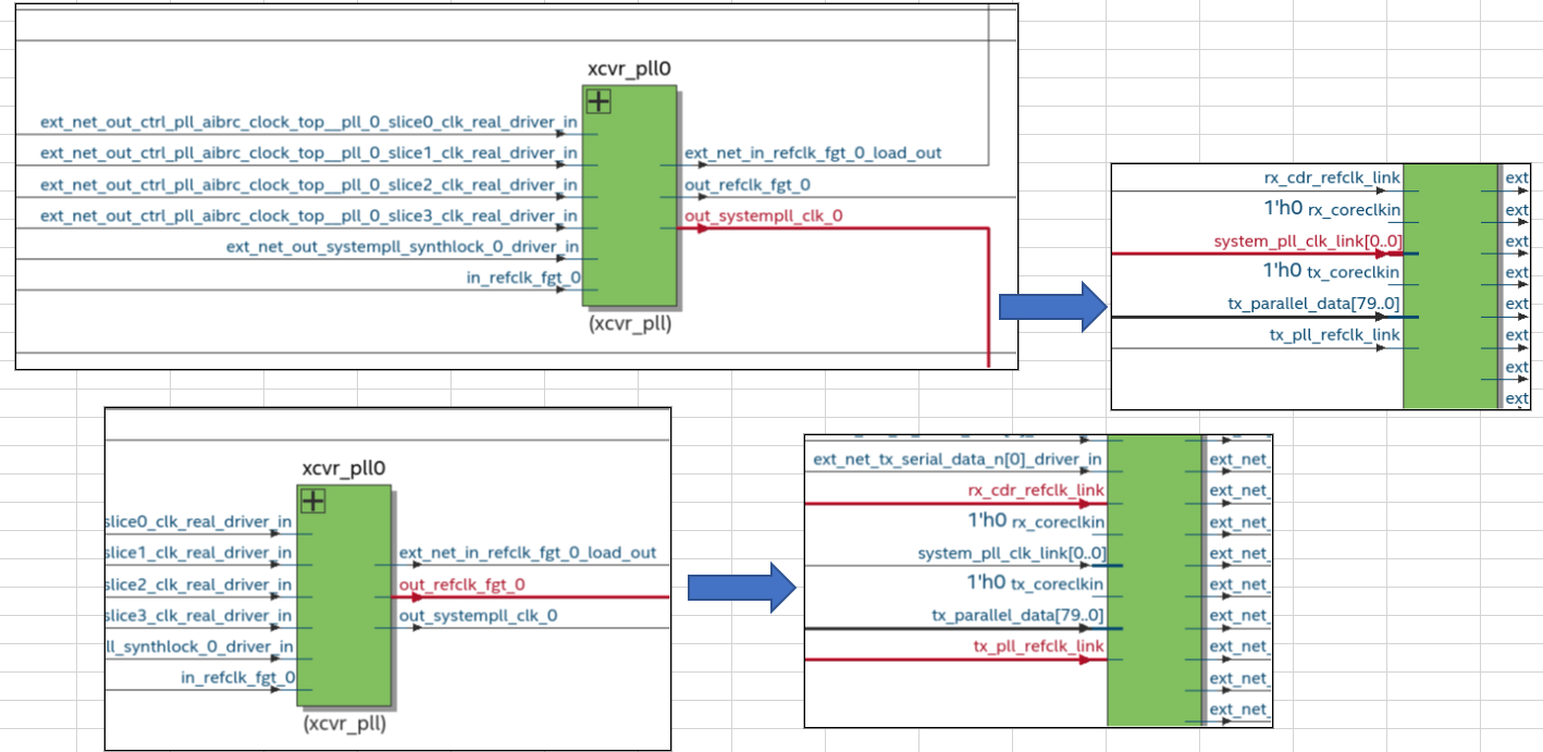
I created a simple testbench to instantiate these components, and generated the simulation script in Quartus 22.4. I loaded all this into mentor's Questasim, but the IP cores aren't doing anything. I've attached a screenshot from Questasim, showing the ports of the IP cores.
In the TX and RX IP cores, the '?x_rst_ack' signals are never asserted, no matter how long I assert the '?x_rst' signals (I've asserted for up to 1000us)
Additionally, the outputs of the Reference and System PLL Clocks are fixed at '1'.
Is there something I need to do to make the F-Tile Reference and System PLL Clocks IP work?
Thank you for your assistance.
Kind regards,
Sam de Jong
Hi Sir
I have checked the user guide, out_systempll_clk_ and out_refclk_fgt_ ports are not supported for simulation, and there is no current plan to support this.
There is a small note that mentioned this in the User Guide (page 110 and 222):
"Ports ending in "_link" must connect to the F-Tile Reference and System PLL Clocks Intel FPGA IP. These ports cannot be simulated."
PDF link to this user guide: https://cdrdv2.intel.com/v1/dl/getContent/683872
The understanding is that the System PLL outputs are not visible in simulation, but they are operating "under the hood". This would explain F-Tile PHY functionality even though the System PLL *appears* to not be functional in simulation.
12 Replies
 skbeh
skbehContributor
Hi
For F-Tile PMA/FEC Direct PHY simulation, you can refer to the 'F-tile Architecture and PMA and FEC Direct PHY IP User Guide', see section "6.7. Simulating the F-Tile PMA/FEC Direct PHY Design"
PDG User Guide link: https://cdrdv2.intel.com/v1/dl/getContent/683872
 SDe_J
SDe_JHi skbeh,system
Thank you for replying. I followed the instruction in that document when I initially tried to setup the simulation, and what I showed was the result of that. The ports Reference and System PLL Clocks IP never changes.
- skbeh
Please ensure you use the latest Quartus version (currently is v 22.4) to generate the example design testbench and run the simulation.
- SDe_J
Yes, I'm using Quartus 22.4.
I am running the simulation in Questasim 2019.2 using the simulation setup scripts generated by Quartus 22.4.
- skbeh
According to the PMA/FEC Direct PHY User Guide:
PDF link: https://cdrdv2.intel.com/v1/dl/getContent/683563Page 219:
The F-Tile Reference and System PLL Clocks Intel FPGA IP is required for F-tile PMA/FEC Direct PHY designs. You must instantiate and connect this IP for simulation and compilation.Page 189:
The F-Tile Reference and System PLL Clocks Intel FPGA IP must always connect to the F-Tile PMA/FEC Direct PHY Intel FPGA IP or protocol IPs. You cannot compile or simulate the F-Tile Reference and System PLL Clocks Intel FPGA IP as a standalone IP.So, please check your testbench to make sure the Reference and System PLL Clocks and PMA/FEC Direct PHY are connected as illustrated in Table 96 of above user guide.
You can also generate an example design from the 'Example Design' tab of the F-Tile PMA/FEC Direct PHY Intel FPGA IP, then you can visualize the connection.
- skbeh
Hi Sir
I have checked the user guide, out_systempll_clk_ and out_refclk_fgt_ ports are not supported for simulation, and there is no current plan to support this.
There is a small note that mentioned this in the User Guide (page 110 and 222):
"Ports ending in "_link" must connect to the F-Tile Reference and System PLL Clocks Intel FPGA IP. These ports cannot be simulated."
PDF link to this user guide: https://cdrdv2.intel.com/v1/dl/getContent/683872
The understanding is that the System PLL outputs are not visible in simulation, but they are operating "under the hood". This would explain F-Tile PHY functionality even though the System PLL *appears* to not be functional in simulation.
- SDe_J
Hi skbeh,
Thank you for the clarification on the system pll. Does this mean the F-tile transceivers cannot be simulated at all?
The understanding is that the System PLL outputs are not visible in simulation, but they are operating "under the hood". This would explain F-Tile PHY functionality even though the System PLL *appears* to not be functional in simulation.
I'm not seeing any functionality from the F-tile PHY IPs in my simulation.
- skbeh
Not sure which QuestaSim version you are using.
Please use Questasim version 2021.4
- SDe_J
I have installed 2021.4 and still get the same result. Attached is the vhdl code which instantiates the transceiver and system Pll IPs. Is there anything obviously wrong? I read the F-tile user guides when I built it.
- skbeh
This article describe about the out_refclk_fgt and out_system_pll_clk ports not toggling.
https://www.intel.com/content/www/us/en/support/programmable/articles/000088803.html
- skbeh
Hi Sir
Please refer to the attached the .zip, ppt, and .wlf files of a functional simulation design for your reference.
Also, refer to the .ppt (page# 36) that include the steps on how to run the simulation.The System PLL is not supported in simulation, so the System PLL output ports will not toggling in simulation. These ports are however functioning under the hood which is evident from the F-tile Direct PHY IP functioning in simulation. The design is with Soft PRBS with RSFEC Demo Design (FGT mode) which also can be found here https://community.intel.com/t5/FPGA-Wiki/High-Speed-Transceiver-Demo-Designs-Agilex-I-Series-F-Tile/ta-p/1315123.
Please note that the simulation takes many hours to complete. - SDe_J
For others that came across this problem, the solution that worked (which I discovered through the example designs provided) is:
- In quartus, run the 'Logic Generation' option in 'Project Overview'
- This will generate a directory called 'support logic'
- Run 'Generate Simulator script for IP'
- In your testbench, add this entity declaration:
- <top-level-entity-name>_auto_tiles_inst : entity <top-level-entity-name>_auto_tiles.<top-level-entity-name>_auto_tiles;
- There are no ports on this entity
- This entity is declared in 'support_logic/<top-level-entity-name>_auto_tiles.sv'
- 'mentor/Modelsim.ini' loads this entity into memory
- Add the top level with it's own name as the entity label:
- e.g., <top-level-entity-name>: entity work.<top-level-entity-name>
- Now you can run the simulation.
- In quartus, run the 'Logic Generation' option in 'Project Overview'