Forum Discussion

 Occasional Contributor
F-tile transceiver IP simulation
 3 years ago
Hi Sir
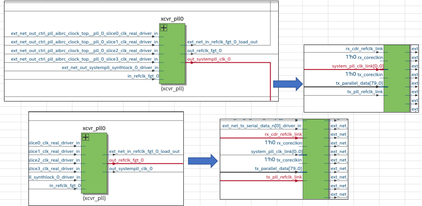
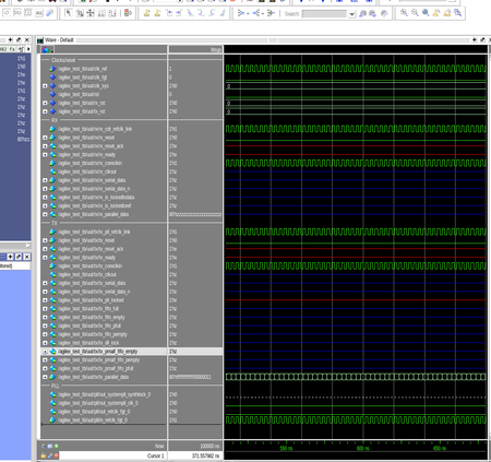
I have checked the user guide, out_systempll_clk_ and out_refclk_fgt_ ports are not supported for simulation, and there is no current plan to support this.
There is a small note that mentioned this in the User Guide (page 110 and 222):
"Ports ending in "_link" must connect to the F-Tile Reference and System PLL Clocks Intel FPGA IP. These ports cannot be simulated."
PDF link to this user guide: https://cdrdv2.intel.com/v1/dl/getContent/683872
The understanding is that the System PLL outputs are not visible in simulation, but they are operating "under the hood". This would explain F-Tile PHY functionality even though the System PLL *appears* to not be functional in simulation.
 Contributor
According to the PMA/FEC Direct PHY User Guide:
PDF link: https://cdrdv2.intel.com/v1/dl/getContent/683563
Page 219:
The F-Tile Reference and System PLL Clocks Intel FPGA IP is required for F-tile PMA/FEC Direct PHY designs. You must instantiate and connect this IP for simulation and compilation.
Page 189:
The F-Tile Reference and System PLL Clocks Intel FPGA IP must always connect to the F-Tile PMA/FEC Direct PHY Intel FPGA IP or protocol IPs. You cannot compile or simulate the F-Tile Reference and System PLL Clocks Intel FPGA IP as a standalone IP.
So, please check your testbench to make sure the Reference and System PLL Clocks and PMA/FEC Direct PHY are connected as illustrated in Table 96 of above user guide.
You can also generate an example design from the 'Example Design' tab of the F-Tile PMA/FEC Direct PHY Intel FPGA IP, then you can visualize the connection.