Forum Discussion

 Occasional Contributor
LTC Connector DE10-Standard FPGA

 Frequent Contributor
Hi greenlantern01 ,
Sorry for the delay in getting back, was out of office for festive holidays and I forgot to get back to you on this, really sorry about that.
May I know what's the latest status on this , whether you manage to find a solution to it?
Actually I didnt get any C code attachment in this thread though, could you kindly reattach your code here?
Since you have already reverted the DTS back to original to be able to boot up, could you try running this command in linux terminal , I'm wondering whether we are toggling the right GPIO, did you have a chance to probe the resistor to the LTC pin to see whether it toggles high low when your code runs?
grep "" /sys/class/gpio/gpiochip*/label
it will list down the gpio controller addresses, can give me the output of that command above?
Thanks
Regards
Kian
Frequent ContributorHi
I'm really sorry for the long delay in my reply on this thread.
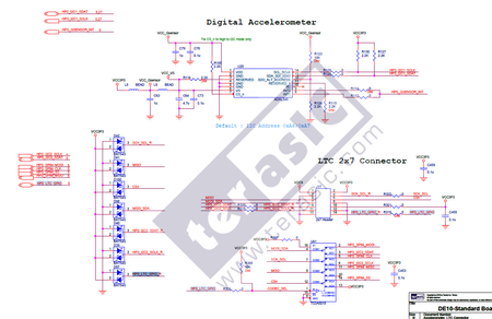
You're still seeing the i2c device 0x53 which is the G-sensor as it is connected on I2C1 line (in the previous comment). On the connection diagram, you wont be able to toggle P14 as the R319 is marked as DNI (do not install) means it is not connected at all thus it is always low at pin14 of the 2x7 header.
Instead you should probe this R306 resistor that connects to the pin 1 of TS3A5018, this is where your i2c2 switch and try your switching app
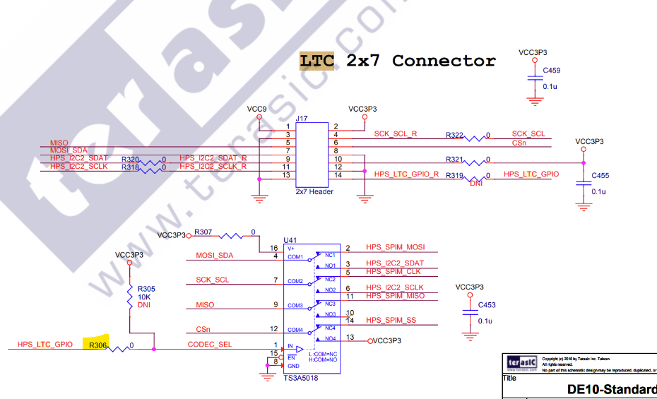
When you mentioned you run your app and could see pin 7 of the 2x7 header toggling, this might be due to the HPS_LTC_GPIO now set to 1 (from your app) and toggles all NC -> NO , in this case if you look at the pin 4 (MOSI_SDA that is connected to pin 7 of the jumper) , you're most likely seeing the switching/toggling effect when you set HPS_LTC_GPIO = 1.
Is your i2c external device connected to pin 9 and 11 of the 2x7 header?
Thanks
Regards
Kian


