Forum Discussion

 Occasional Contributor
LTC Connector DE10-Standard FPGA
I am trying to access the I2C bus on the LTC connector on the DE10 Standard FPGA board.
I have enabled the i2c controllers on the HPS.
How do I now gain access to the i2c2 pins that are connected to the ltc connector from the HPS?
I was able to communicate to the g-sensor that shares the same bus with the ltc connector, but I need to access the LTC connector to communicate with a separate board.
I see that there is a TS3A5018 switch. Am I required to set the HPS_LTC_GPIO to low to switch communication from spi to i2c?
Kindly help.
24 Replies
 greenlantern01
Hi Kian,
I tried working on the solution provided.
I appended the dts file as shown below:
Added the i2c1 device and then converted the dts file to dtb as shown in the document. Copied the dtb file on the sd card and tried to boot the fpga however, I think it crashes at boot.
It doesn't go beyond this point.
Kindly direct on the next steps.
Thank you & Regards
 KianHinT_altera
Frequent Contributor
Thanks for the reply. I will be out of office next week for a week thus response will be slower.
Regards
Kian
- greenlantern01
Hi Kian,
I was wondering if you got a chance to have a look into this.
Any help would be highly appreciated!
Regards
- KianHinT_altera
Hi greenlantern01,
Really sorry for the delay in getting back, was going through my mails after back to office , missed out on the notification.
From the screenshot, seems it is resetting during kernel loading stage, probably some settings in the dts.
I was checking back on Terasic schematic and notice that there is some differences between DE10-Standard Rev C and Rev D board. Could you help confirm you board revision ( i suppose to be rev C because in schematic I still see the digital accelerometer and HPS_LTC_GPIO connected to TS3A5018, Rev D schematic all these been removed)
Anyway if you're on Rev C, disregard the DTS changes you made first, and
1. Measure the HPS_LTC_GPIO ( can probe R306 resistor and check whether it toggles or switch just to check the pin logic )
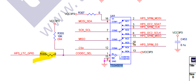
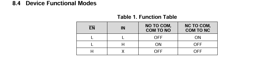
I got this from the TS3A5018 datasheet (but the table here seems to indicate the other way round for NO/NC)
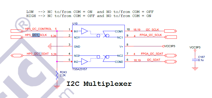
From schematic, Gsensor/ digital accelerometer is connected to I2C1 which looks like it is connected to different pin all together , not via TS3A5018 , thus you always can talk to Gsensor regardless of the LTG connector.
After verifying the LTC_GPIO toggles correctly, probably can check whether Linux side have these i2C drivers already initialized, if yes maybe no need add the i2c2 in the DTS for linux-socfpga
Try this command to list the i2c : i2cdetect -l
You should see something like Synopsys DesignWare
scan the bus to see whether gsensor and your ltc shows up
i2cdetect -y -r <bus number from the list, 0,1,2>
This one to confirm that i2c has gsensor and your LTC device connected.
Thanks
Regards
Kian
- KianHinT_altera
Hi,
Just wondering what's the status on this case , whether the issue been resolved?
Thanks
Regards
Kian
- greenlantern01
Hi Kian,
I'm still working on this issue.
Regards
- greenlantern01
I was able to figure out the way to control the HPS GPIO using the GPIO controllers. HPS_LTC_GPIO is at GPIO40 and HPS_LED is at GPIO53.
GPIO[57:29] are controlled by GPIO1 Controller. Below is the address map for the GPIO controllers:
I wrote a C program to be able to control the LED and set the HPS_LTC_GPIO to low. The code works for blinking the HPS LED. It should also work for the HPS_LTC_GPIO and I should be able to access the I2C bus on the LTC Connector, however, the HPS still communicates with the Gsensor.
Could you suggest what other things I could try?
I have attached my code to this message.
- KianHinT_altera
Sorry for the delay in responding back, is it possible for you to probe the physical HPS_LTC_GPIO/GPIO40 to see whether it toggles when your code set the pin to low to confirm whether it is switching (via multimeter ?)
How about the I2C2 pin mux settings? Pins are assigned to HPS ?
Did a search on past topics and looks like there is some discussion on the clock , see whether is it similar issue
https://community.altera.com/discussions/fpga-device/how-change-i2c-clock-on-cyclone-v-hps--terasic-de10-nano/266788
Thanks
Regards
Kian
- greenlantern01
Hello Kian,
Thanks for sharing this information. I will work on it and give an update on this.
Regards
- greenlantern01
According to the schematic, since the HPS_LTC_GPIO at GPIO40, I exported the GPIO40 of HPS from the Platform designer and connected it with the HPS_LTC_GPIO in my top level design.
Could you kindly guide me on how to switch it to low?
What would be the address of the GPIO40 that I can access from Linux to set the GPIO40 to low?
- KianHinT_altera
Hi greenlantern01 ,
Judging from the schematic , the signals on the LTC connector are multiplexed between SPI and I2C through the TS3A5018 switch which is controlled by the HPS_LTC_GPIO , you will need to set it to Low to switch to I2C2 pins
Thanks
Regards
Kian


