soc devkit
28 Topics
Agilex 5 E-Series 065B Premium Dev Kit - is FPGA_3V3_SDA/SCL driven by an HPS I2C controller?
Board: Agilex 5 E-Series 065B Premium Dev Kit (A5ED065BB32A) In the schematic, FPGA_3V3_SDA/SCL (U402 MAC EEPROM at 0x56/0x5E, QSFP1/2 at 0x50) goes to Bank 5A HVIO pins (page 17), not to the dedicated HPS_IOA/IOB I2C pins (page 12). So my understanding is that an HPS I2C controller can drive this bus only if it is routed to the FPGA fabric in the HPS IP, or if a soft I2C master drives it. Questions: 1. Is that correct, and does the kit's reference design connect an HPS I2C or a soft I2C IP to these pins? 2. How do I confirm which controller drives these pins in Quartus Prime software and at runtime in Linux? Thanks,80Views0likes1Comment
Workaround for TCK frq. limitations on USB-Blaster I/II/III & Clones (fixing "JTAG chain broken")
Workaround for TCK frequency limitations on USB-Blaster I/II/III and clones (fixing "JTAG chain broken") Hi everyone, I'd like to share a practical workaround for a problem many of us run into when programming Altera FPGAs through test fixtures, level shifters or long ribbon cables. **The problem** In these setups, "JTAG chain broken" or "Unable to scan device chain" errors are common. They are usually caused by signal reflections and poor termination on custom boards and long extensions. Lowering the TCK frequency is the standard remedy, but the options are limited: - USB-Blaster I (and most low-cost clones) runs at a fixed TCK of about 6 MHz. Quartus offers no way to change it. - USB-Blaster II can be set to 6/16/24 MHz via `jtagconfig --setparam <cable> JtagClock <freq>`, but nothing below 6 MHz. In practice this setting is also unreliable: it is not persistent and can fall back to the 24 MHz default (see Altera KB: "Why does the TCK frequency setting of the USB-Blaster II download cable revert to the default value of 24 MHz after being changed?"). In our experience it is a constant source of trouble, especially in production where it has to be set again and again. For really marginal lines, 6 MHz is often still too fast. **The workaround** Disclosure: I'm the developer of the tool described below, so please take this as information from the vendor. Quintus Programmer (by Dution) drives the JTAG lines of the USB-Blaster in bit-bang mode instead of using the adapter's fixed shift clock. This lets you choose the TCK frequency freely, e.g. down to 100 kHz, with the same USB-Blaster I/II/III or clones you already have. With a lower TCK, programming and verification become stable again on long or poorly terminated lines without any hardware changes. The standard USB-Blaster driver stays in place, and Quintus only replaces the programming step. **Before reaching for software, check the hardware basics** The recommendations from the Altera Knowledge Base still apply and often fix the problem on their own: - TCK pull-down 1 kΩ to GND, TMS/TDI pull-up 10 kΩ to VCCIO - a small capacitor (10–22 pF) at TCK near the FPGA against ringing edges - a TCK buffer on long or noisy lines If the layout can't be changed, a lower TCK is a practical way out. More info: search for "Quintus Programmer Dution". Happy to answer technical questions here.171Views0likes2Comments
Introducing the Altera Community AI Responder — Beta
Altera is introducing the AI Responder, an assistant built into the Altera Community to help provide faster, context-aware guidance for Altera product questions. It uses relevant public Altera documentation and Knowledge Database content, with coverage continuing to expand. The AI Responder may provide source references and can hand off complex or out-of-scope questions to an Altera subject-matter expert. As a beta feature, responses may contain errors or omissions, so please review the sources and verify technical guidance against official Altera documentation before implementation. If the response does not fully address your question, add more context and tag ai_responder to continue the discussion. We welcome your feedback as we improve the Community experience.19Views0likes0Comments
Design of MAX V CPLD 5M2210 System Controller in Arria 10 SoC board
Hi Altera, Could you help to share the MAX V CPLD 5M2210 System Controller with me? We're in AI research work with Arria 10 SoC board and need the source code of system maxV but is not included in the installer package, arria10_10as066n3f40_soc_v15.1.2.zip. Thank you!433Views0likes7CommentsPCIe Root Complex on DK-A5E013BM16AEA
Hello everyone, I have an Agilex 5 development board, the DK-A5E013BM16AEA. This board has a PCI Express connector that is compatible with the Raspberry Pi 5. I am wondering whether it would be possible to use a PCIe board designed for the Raspberry Pi 5 from the Agilex 5 HPS (ARM Cortex-A78) through this connector. Unfortunately, this PCI Express connector is not directly connected to the HPS. In other words, it seems necessary to implement a bridge between the HPS and PCIe using Quartus, and to program the FPGA as user logic. Does anyone have any reference information that could help with implementing a PCIe Root Complex on this development board, the DK-A5E013BM16AEA? Thank you very much.Solved92Views0likes3Comments
Agilex™ 7 FPGA M-Series Development Kit_HBM2e Edition_REVB2_Altera
Hi, This is regarding the clock tree used in the Agilex 7 FPGA M-Series Development Kit. I have a few questions and would appreciate your clarification. 1. Why is the 390.625 MHz SyncE clock generated by the Si5518 (U92) provided to the Si5395 (U14) and subsequently routed through the Si5391 devices to the DDR5 and HBM reference clock pins of the Agilex M FPGA? 2. Why is the output of Si5391 (U35) connected to an input of another Si5391 (U93), and similarly, why is an output of U93 connected back to an input of U35? What is the purpose of these interconnections? 3. Why is the 312.5 MHz LVDS SAMPLE clock output from the Si5518 connected to the ToD block of the Agilex M FPGA? What function does this signal serve in the ToD block? 4. In the Si5518, why is the PPS output looped back to one of the PLL inputs (1PPSFB)? What is the purpose of this feedback connection in the schematic? 5. Similar loopback connections are also observed in Bank 13C of the Agilex M FPGA. Why is this loopback connection required ? I would appreciate your response to these queries. Any pointers to relevant documentation or application notes would also be very helpful Regards, Thulasi110Views0likes3Comments
LLM Implementation on Agilex 5 E-Series 065B Modular Dev Kit
I am currently working on deploying Large Language Model (LLM) inference using FPGA AI Suite on the Agilex 5 E-Series 065B Modular Development Kit. I have two clear and specific questions: Is the Agilex 5 E-Series 065B officially supported for LLM / Transformer inference with FPGA AI Suite? Is the following workflow officially supported for LLM inference on this board? Step 1: Export a pre-trained LLM from Hugging Face to OpenVINO IR format using optimum-intel Step 2: Generate the target FPGA architecture file using architecture_optimizer for Agilex 5. Step 3: Compile the OpenVINO IR model for the FPGA using: • dla_compiler → for Sequential flow, or • Spatial Compiler → for Spatial flow. Step 4: Integrate the generated FPGA AI Suite IP into a Quartus Prime project, generate the bitstream, and program it onto the Agilex 5 E-Series 065B board. Step 5: Run inference using the FPGA AI Suite runtime (host application). I understand this may not be a push-button process and could require significant modifications to the generated RTL — but is this workflow still considered a viable starting point for implementing LLM / Transformer inference on the Agilex 5 E-Series 065B? Thank you.83Views0likes0CommentsFitter error in A5ED043AB23AI2V Example design
Hi, I have tried using the example design of the A5ED065BB32AE4SR0 development kit and modified the part number to A5ED043AB23AI2V. During compilation, I am encountering a fitter error when both PCIe and USB 3.1 are enabled together. However, I am able to compile successfully when using each interface individually. Could you please help me understand how to resolve this issue?171Views0likes6CommentsAccess to System MAX design for Agilex 5 kit
For the Agilex 7 I-Series Transceiver-SoC Development Kit (DK-SI-AGI027Fx), the design source for the on-board System MAX10 device is included in the installer package, under examples. For the Agilex 5 E-Series 065B Premium Development Kit (DK-A5E065BB32AEx) it is not. Is the System MAX design for the Agilex 5 kit available from somewhere else? If not, is that because of the preliminary status of that kit, or will that design never be made available?Solved212Views0likes6CommentsArrow AXE5 Eagle Board JTAG issue
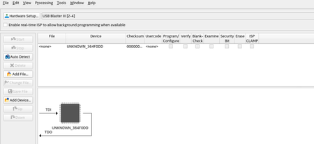
Hi, I have an AXE5 eagle board. The Quartus Programmer on Auto-Detect does show the usb blaster3 but the device is named UNKNOWN_364F0DD instead of A5ED065BB32AES4. What do you think could be the issue? BTW I am on Linux RHEL 8. I am using Arrow blaster and used FTProg to flash it as USB Blaster 3 as suggested by guide120Views0likes2Comments