Forum Discussion

JPlus New Contributor
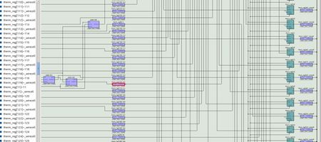
7 years agoNew ContributorWhy does Quartus put a LE buffer cell in series with the output of an LE cell (adder cell) and the input to the downstream FF? See highlighted element in schematic. Is there a way to disable this?

JPlusNew Contributor
7 years agoNew ContributorThe default mode is to optimize hold timing for ALL paths. Anyway, this is not the problem and I set it back to the default.
I removed the logic lock region and the tool started placing TWO buffers in series between the adder and FFs??? Why is it doing this?
So are you saying that this is uncommon, for buffers to be added to paths like this? I get the impression from you that this is NOT supposed to happen.
BTW: How do you instruct the tool that a signal that it has identified as a Clock is NOT a clock. I read somewhere that you can specify 'not a clock' in the Assignment editor but that option does not appear to available.


