Forum Discussion

Altera_Forum Honored Contributor
11 years agoHonored ContributorRequest for help in VHDL troubleshooting
Hi all,
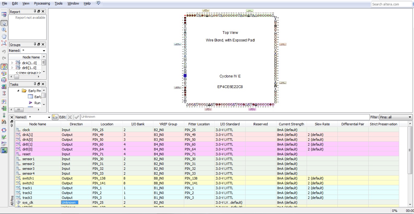
I am a new to programming of VHDL to FPGA. Recently tried experimenting with a code from a book and during simulation, it was functioning perfectly. However after i programmed into Altera Cyclone IV EP4CE chip, the chip is always stuck at the default state regardless of the input. Was suspecting that the clock input is not configured properly thus i assigned the clock to Pin25 and yet it is not helping. Hope anyone can lend a helping hand to help troubleshoot.:(:confused: Thanks alot in advance. The code: LIBRARY IEEE; USE IEEE.STD_LOGIC_1164.ALL; USE IEEE.STD_LOGIC_ARITH.ALL; USE IEEE.STD_LOGIC_UNSIGNED.ALL; ENTITY Traincollision IS PORT( reset, clock, sensor1, sensor2, sensor3, sensor4 : IN STD_LOGIC; switch1, switch2 : OUT STD_LOGIC; track1, track2, track3 : OUT STD_LOGIC; dirA, dirB : OUT STD_LOGIC_VECTOR( 1 DOWNTO 0 )); END Traincollision; ARCHITECTURE a OF Traincollision IS TYPE STATE_TYPE IS ( ABout, Ain, Bin, Astop, Bstop ); SIGNAL state: STATE_TYPE; SIGNAL sensor12, sensor13, sensor24 : STD_LOGIC_VECTOR(1 DOWNTO 0); BEGIN PROCESS ( reset, clock ) BEGIN IF reset = '1' THEN state <= ABout; ELSIF clock'EVENT AND clock = '1' THEN CASE state IS WHEN ABout => CASE Sensor12 IS WHEN "11" => state <= About; WHEN "10"=> state <= Bin; WHEN "01" => state <= Ain; WHEN "00"=> state <= Ain; WHEN OTHERS => state <= ABout; END CASE; WHEN Ain => CASE Sensor24 IS WHEN "11" => state <= Ain; WHEN "10" => state <= ABout; WHEN "01" => state <= Bstop; WHEN "00" => state <= ABout; WHEN OTHERS => state <= ABout; END CASE; WHEN Bin => CASE Sensor13 IS WHEN "11" => state <= Bin; WHEN "10" => state <= ABout; WHEN "01" => state <= Astop; WHEN "00" => state <= About; WHEN OTHERS => state <= ABout; END CASE; WHEN Astop => IF Sensor3 = '0' THEN state <= Ain; ELSE state <= Astop; END IF; WHEN Bstop => IF Sensor4 = '0' THEN state <= Bin; ELSE state <= Bstop; END IF; END CASE; END IF; END PROCESS; sensor12 <= sensor1 & sensor2; sensor13 <= sensor1 & sensor3; sensor24 <= sensor2 & sensor4; Track1 <='0'; WITH state SELECT Track3 <= '1' WHEN ABout, '1' WHEN Ain, '1' WHEN Bin, '1' WHEN Astop, '1' WHEN Bstop; WITH state SELECT Track2 <= '0' WHEN ABout, '0' WHEN Ain, '1' WHEN Bin, '1' WHEN Astop, '0' WHEN Bstop; WITH state SELECT Switch1 <= '0' WHEN ABout, '0' WHEN Ain, '1' WHEN Bin, '1' WHEN Astop, '0' WHEN Bstop; WITH state SELECT Switch2 <= '0' WHEN ABout, '0' WHEN Ain, '1' WHEN Bin, '1' WHEN Astop, '0' WHEN Bstop; WITH state SELECT DirA <= "01" WHEN ABout, "01" WHEN Ain, "01" WHEN Bin, "00" WHEN Astop, "01" WHEN Bstop; WITH state SELECT DirB <= "01" WHEN ABout, "01" WHEN Ain, "01" WHEN Bin, "01" WHEN Astop, "00" WHEN Bstop; END a;20 Replies
 Altera_Forum--- Quote Start --- Your diagram shows that the reset signal is constant '1' - why? --- Quote End --- Hi tricky, good observation.. I have set it to active '0' instead..
- Altera_Forum
Could you show us your new code? (put it between
tags to preserve formatting) There seems to be some inconsistencies between the code and the signaltap screenshot. Also you should start with a proper reset pulse before putting some signals on the sensors, to be sure you start in a correct state.and - Altera_Forum
Hi there, sorry for the late reply.
Was tied up with work. Below is the code for the program. I tried signaltap on it and upon toggling the sensor 1/2, i was expecting it to enter into Ain/Bin state. But yet it seem to only trigger at the first try after reset. The subsequent tries has no response. Can help advise? Thanks alot!LIBRARY IEEE; USE IEEE.STD_LOGIC_1164.ALL; USE IEEE.STD_LOGIC_ARITH.ALL; USE IEEE.NUMERIC_STD.all; ENTITY Tcontrol1 IS PORT( reset, clock, sensor1, sensor2, sensor3, sensor4 : IN STD_LOGIC; switch1, switch2, switch1a, switch2a : OUT STD_LOGIC; track1, track2, track3 : OUT STD_LOGIC; dirA, dirB : OUT STD_LOGIC_VECTOR( 1 DOWNTO 0 )); END Tcontrol1; ARCHITECTURE a OF Tcontrol1 IS TYPE STATE_TYPE IS ( ABout, Ain, Bin, Astop, Bstop ); SIGNAL state: STATE_TYPE; SIGNAL sensor12, sensor13, sensor24 : STD_LOGIC_VECTOR(1 DOWNTO 0); BEGIN PROCESS ( reset, clock ) BEGIN IF reset = '0' THEN state <= ABout; ELSIF clock'EVENT AND clock = '1' THEN CASE state IS WHEN ABout => CASE Sensor12 IS WHEN "11" => state <= About; WHEN "10"=> state <= Bin; WHEN "01" => state <= Ain; WHEN "00"=> state <= Ain; WHEN OTHERS => state <= ABout; END CASE; WHEN Ain => CASE Sensor24 IS WHEN "11" => state <= Ain; WHEN "10" => state <= ABout; WHEN "01" => state <= Bstop; WHEN "00" => state <= ABout; WHEN OTHERS => state <= ABout; END CASE; WHEN Bin => CASE Sensor13 IS WHEN "11" => state <= Bin; WHEN "10" => state <= ABout; WHEN "01" => state <= Astop; WHEN "00" => state <= About; WHEN OTHERS => state <= ABout; END CASE; WHEN Astop => IF Sensor3 = '0' THEN state <= Ain; ELSE state <= Astop; END IF; WHEN Bstop => IF Sensor4 = '0' THEN state <= Bin; ELSE state <= Bstop; END IF; END CASE; END IF; END PROCESS; sensor12 <= sensor1 & sensor2; sensor13 <= sensor1 & sensor3; sensor24 <= sensor2 & sensor4; Track2 <='0'; WITH state SELECT Track3 <= '0' WHEN ABout, '0' WHEN Ain, '0' WHEN Bin, '0' WHEN Astop, '1' WHEN Bstop; WITH state SELECT Track1 <= '0' WHEN ABout, '0' WHEN Ain, '0' WHEN Bin, '1' WHEN Astop, '0' WHEN Bstop; WITH state SELECT Switch1 <= '0' WHEN ABout, '0' WHEN Ain, '1' WHEN Bin, '1' WHEN Astop, '0' WHEN Bstop; WITH state SELECT Switch2 <= '0' WHEN ABout, '0' WHEN Ain, '1' WHEN Bin, '1' WHEN Astop, '0' WHEN Bstop; WITH state SELECT Switch1a <= '1' WHEN ABout, '1' WHEN Ain, '0' WHEN Bin, '0' WHEN Astop, '1' WHEN Bstop; WITH state SELECT Switch2a <= '1' WHEN ABout, '1' WHEN Ain, '0' WHEN Bin, '0' WHEN Astop, '1' WHEN Bstop; WITH state SELECT DirA <= "01" WHEN ABout, "01" WHEN Ain, "01" WHEN Bin, "00" WHEN Astop, "01" WHEN Bstop; WITH state SELECT DirB <= "01" WHEN ABout, "01" WHEN Ain, "01" WHEN Bin, "01" WHEN Astop, "00" WHEN Bstop; END a; - Altera_Forum
have you got a testbench for this code, rather than trying to debug it on hardware (which takes much much longer)
- Altera_Forum
- Altera_Forum
it seems You should check sensor4 )
andsensor24 <= sensor2 & sensor4WHEN Ain => CASE Sensor24 IS WHEN "11" => state <= Ain; WHEN "10" => state <= ABout; WHEN "01" => state <= Bstop; WHEN "00" => state <= ABout; WHEN OTHERS => state <= ABout; END CASE; - Altera_Forum--- Quote Start --- it seems You should check sensor4 )
andsensor24 <= sensor2 & sensor4
--- Quote End --- Hi Alex96, Thanks for the pointers. Mind sharing the concerns with sensor4?WHEN Ain => CASE Sensor24 IS WHEN "11" => state <= Ain; WHEN "10" => state <= ABout; WHEN "01" => state <= Bstop; WHEN "00" => state <= ABout; WHEN OTHERS => state <= ABout; END CASE; - Altera_Forum--- Quote Start --- Hi Tricky, Is this considered testbench? --- Quote End --- No - this is a waveform from a simulator. How are you producing the waveform?
- Altera_Forum--- Quote Start --- Hi there, sorry for the late reply. Was tied up with work. Below is the code for the program. I tried signaltap on it and upon toggling the sensor 1/2, i was expecting it to enter into Ain/Bin state. But yet it seem to only trigger at the first try after reset. The subsequent tries has no response. Can help advise? Thanks alot!
--- Quote End --- Forgot to add on that the sensor circuitry are active low. When they are triggered, they goes low.LIBRARY IEEE; USE IEEE.STD_LOGIC_1164.ALL; USE IEEE.STD_LOGIC_ARITH.ALL; USE IEEE.NUMERIC_STD.all; ENTITY Tcontrol1 IS PORT( reset, clock, sensor1, sensor2, sensor3, sensor4 : IN STD_LOGIC; switch1, switch2, switch1a, switch2a : OUT STD_LOGIC; track1, track2, track3 : OUT STD_LOGIC; dirA, dirB : OUT STD_LOGIC_VECTOR( 1 DOWNTO 0 )); END Tcontrol1; ARCHITECTURE a OF Tcontrol1 IS TYPE STATE_TYPE IS ( ABout, Ain, Bin, Astop, Bstop ); SIGNAL state: STATE_TYPE; SIGNAL sensor12, sensor13, sensor24 : STD_LOGIC_VECTOR(1 DOWNTO 0); BEGIN PROCESS ( reset, clock ) BEGIN IF reset = '0' THEN state <= ABout; ELSIF clock'EVENT AND clock = '1' THEN CASE state IS WHEN ABout => CASE Sensor12 IS WHEN "11" => state <= About; WHEN "10"=> state <= Bin; WHEN "01" => state <= Ain; WHEN "00"=> state <= Ain; WHEN OTHERS => state <= ABout; END CASE; WHEN Ain => CASE Sensor24 IS WHEN "11" => state <= Ain; WHEN "10" => state <= ABout; WHEN "01" => state <= Bstop; WHEN "00" => state <= ABout; WHEN OTHERS => state <= ABout; END CASE; WHEN Bin => CASE Sensor13 IS WHEN "11" => state <= Bin; WHEN "10" => state <= ABout; WHEN "01" => state <= Astop; WHEN "00" => state <= About; WHEN OTHERS => state <= ABout; END CASE; WHEN Astop => IF Sensor3 = '0' THEN state <= Ain; ELSE state <= Astop; END IF; WHEN Bstop => IF Sensor4 = '0' THEN state <= Bin; ELSE state <= Bstop; END IF; END CASE; END IF; END PROCESS; sensor12 <= sensor1 & sensor2; sensor13 <= sensor1 & sensor3; sensor24 <= sensor2 & sensor4; Track2 <='0'; WITH state SELECT Track3 <= '0' WHEN ABout, '0' WHEN Ain, '0' WHEN Bin, '0' WHEN Astop, '1' WHEN Bstop; WITH state SELECT Track1 <= '0' WHEN ABout, '0' WHEN Ain, '0' WHEN Bin, '1' WHEN Astop, '0' WHEN Bstop; WITH state SELECT Switch1 <= '0' WHEN ABout, '0' WHEN Ain, '1' WHEN Bin, '1' WHEN Astop, '0' WHEN Bstop; WITH state SELECT Switch2 <= '0' WHEN ABout, '0' WHEN Ain, '1' WHEN Bin, '1' WHEN Astop, '0' WHEN Bstop; WITH state SELECT Switch1a <= '1' WHEN ABout, '1' WHEN Ain, '0' WHEN Bin, '0' WHEN Astop, '1' WHEN Bstop; WITH state SELECT Switch2a <= '1' WHEN ABout, '1' WHEN Ain, '0' WHEN Bin, '0' WHEN Astop, '1' WHEN Bstop; WITH state SELECT DirA <= "01" WHEN ABout, "01" WHEN Ain, "01" WHEN Bin, "00" WHEN Astop, "01" WHEN Bstop; WITH state SELECT DirB <= "01" WHEN ABout, "01" WHEN Ain, "01" WHEN Bin, "01" WHEN Astop, "00" WHEN Bstop; END a; - Altera_Forum
my Advice: after source will be compiled You should open RTLViewer and StateMachineViewer. Try to make analysis step-by-step. Then compare to your waveforms.