OJin0 Occasional Contributor
Occasional ContributorOccasional ContributorI use Quartus (Quartus Prime 19.1) Lite Edition.
The attached 32-bit counter symbol outputs a duty 50 waveform from t1 to t8, but a narrow waveform from t9 to t31. JOS_COUNT_4_CiRs are all the same.
Is there any reason why the actual behavior in this symbol is different from the schematic?
Best regards,
Oksang
 Regular Contributor
Hi,
The attached 32-bit counter symbol outputs a duty 50 waveform from t1 to t8, but a narrow waveform from t9 to t31. JOS_COUNT_4_CiRs are all the same.
Could you explain the above behaviour in details?Are you simulating the JOS_counter_32.bsf and JOS_counter_32.bdf? Could you share the screenshot of the result and testbench?
Thanks.
Best regards,
KhaiY
Occasional ContributorHello, thanks for the reply.
The schematic and simulation waveform of JOS_counter_32 are captured and a picture is attached.
I am correcting some posts in the question; Correct t0 to t7 as normal waveforms and t8 to t31 as abnormal waveforms. It was not confirmed after t13.
Best regards,
Oksang
Occasional ContributorIt was confirmed to be the same as the simulation wave in the GPIO of 10M08SCU169C8G.
Occasional ContributorOccasional ContributorThe reason JOS_counter_32 behaved abnormally was my mistake.
The module JOS_COUNT_4_CiRs used in JOS_counter_32 has been found to be misdesigned. I misunderstood Carry's concept and designed it.
Now it is working fine. The JOS_COUNT_4xor_CiRs module that works normally is attached.
The reason I designed the JOS_counter_32 module is because LMP-COUNTER (COUNTER_14) does not work, and it is limited to 8 bits by JOS_counter_32, but I have confirmed that the system works.
Is there a problem with my PC?
Or, is the installed Quartus Prime 19.1 installed incorrectly?
If the module is normal, is it a compiler problem?
What can I offer you for review?
Best regards,
Oksang
Regular ContributorHi,
I understand that the waveform issue has been resolved.
I tried to create a LPM_COUNTER, the maximum width supported is 256. You mentioned that the LPM-COUNTER IP does not work and it is limited to 8 bits. May I know what error you see? Is it a compilation error? Could you share the error message and steps to reproduce the error?
Thanks.
Best regards,
KhaiY
Occasional ContributorHello,
The error message could not be saved at the time the error occurred.
Reproducing it today, it is working fine.
At that time, there was no waveform of all output bits.
In the current project, everything is operating normally, so it seems that the past state cannot be reproduced.
So, I am checking with the new project "ElectricPiano_00_00", but the problem is also confirmed in this project.
Thank you.
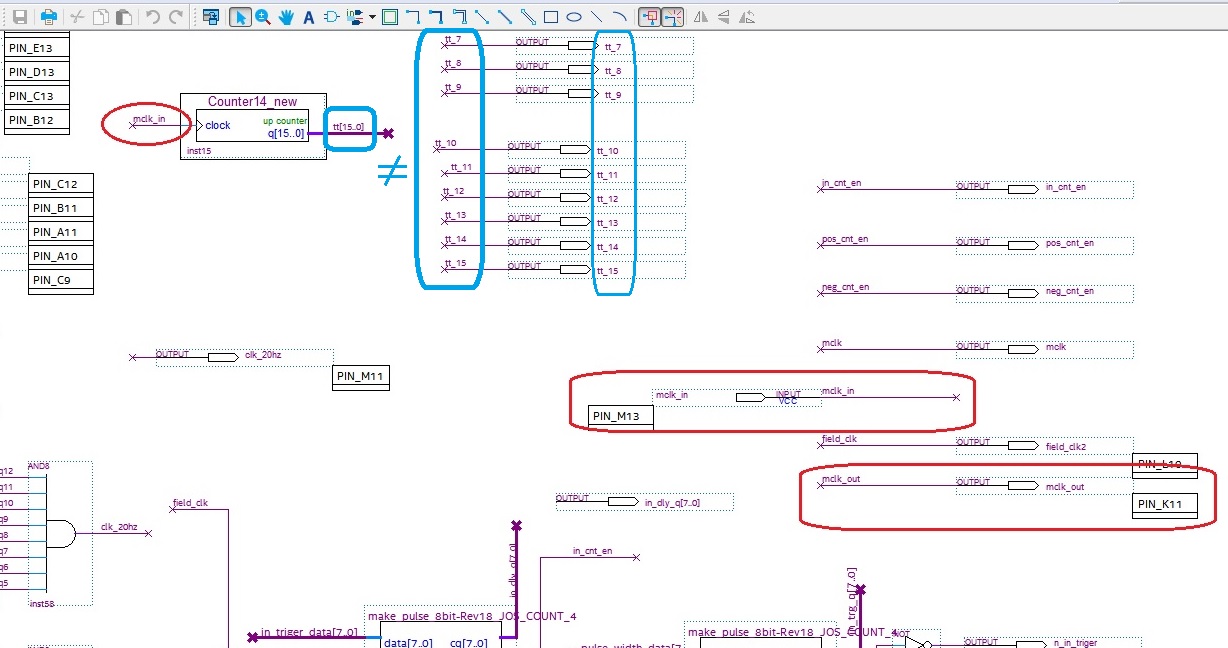
Occasional ContributorIn the reply I wrote earlier, in the Counter_14 test schematic, I have now found that the output pin is connected incorrectly. There was no signal from the simulation to the output pin (tt_xx) due to incorrect pin assignment. (See the blue box in the attached file)
After modifying the Pin Name, it was simulated as a normal waveform.
In this test, there was a problem with pin assignment.
A few days ago, I have been suspicious of my computer. Because my computer was very feverish, I had less fever after installing the termination plug on an unused USB port.
In addition, the mouse pointer does not move during use, and it is often stopped, and just before the mouse pointer starts moving, the computer speaker makes a low volume connection sound every time.
So, I am only designing with Schematic.
So I am designing all the symbols I need for my project directly with Schematic.
When I was using Quarters Prime, I thought I might have some kind of data modification inside my invisible, so I contacted the Intel forum.
Thanks for your reply.
Best regards,
Oksang
Regular ContributorHi OKsang,
I understand that the error cannot be reproduced again in JOS_counter_32 design, everything is working as expected now.
Regarding the ElectricPiano_00_00 design, you mentioned that the problem had occured in this design too. May I know whether the error is referring to simulation error or LPM_COUNTER generation error?
Thanks.
Best regards,
KhaiY
Occasional ContributorRegular ContributorHi OKsang,
Sure. Thanks for the update. I notice that this new question regarding the ElectricPiano_00_00 project is tracked in another post https://forums.intel.com/s/question/0D50P00004fZip3SAC/new-project-electricpiano0000-request-a-review-of-whats-wrong. My colleague will assist you on this new question in the new post.
Thanks.
Best regards,
KhaiY