OJin0 Occasional Contributor
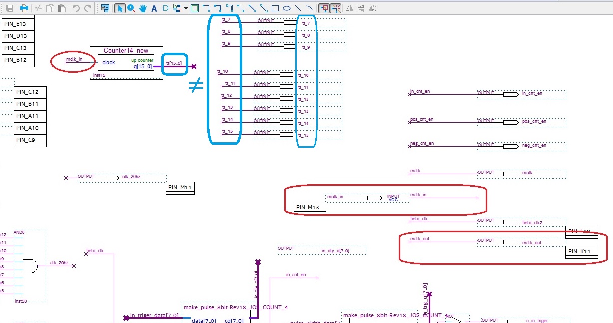
Occasional ContributorOccasional ContributorOccasional ContributorIn the reply I wrote earlier, in the Counter_14 test schematic, I have now found that the output pin is connected incorrectly. There was no signal from the simulation to the output pin (tt_xx) due to incorrect pin assignment. (See the blue box in the attached file)
After modifying the Pin Name, it was simulated as a normal waveform.
In this test, there was a problem with pin assignment.
A few days ago, I have been suspicious of my computer. Because my computer was very feverish, I had less fever after installing the termination plug on an unused USB port.
In addition, the mouse pointer does not move during use, and it is often stopped, and just before the mouse pointer starts moving, the computer speaker makes a low volume connection sound every time.
So, I am only designing with Schematic.
So I am designing all the symbols I need for my project directly with Schematic.
When I was using Quarters Prime, I thought I might have some kind of data modification inside my invisible, so I contacted the Intel forum.
Thanks for your reply.
Best regards,
Oksang