Forum Discussion

 Occasional Contributor
Constraint for phase-shifted external clock (Specifying Clock Waveform Edges)
- 2 years ago
After looking at the Board Configuration, I believe this is Source-Synchronous Interface.
You may refer to the AN 433: Constraining and Analyzing Source-Synchronous Interfaces, section "Input Clock Constraints" on how to constraint the clock.
With the current clock constraints you have, they are not synchronous with each other. Therefore, meeting either the phase-shift or frequency requirement cannot fulfill both requirements simultaneously.
One approach I can suggest is to write a clock constraint in such a way that Quartus treats this as a PLL, ensuring that both clocks are synchronous with each other.
Regards,
Richard Tan

 Super Contributor
Since these clocks are external clock, use create_clock (without the -target), to add a virtual clock for the I/O interface.
example: create_clock -period 5.0 -name dac_clk_ext
Note that I did not apply these clocks to anything in the FPGA, which is what makes them virtual clocks; they exist outside of the FPGA.
Manually phase-shifting a clock, usually done with a PLL. Try to use the create_generated_clock so that the generated clocks are related, so crossings between them are not asynchronous.
# Create a virtual clock, and two generated clocks that derive from it.
# This makes the generated clocks related, so crossings between them are not asynchronous.
create_clock -period 10 -name virtual_base
create_generated_clock -master_clock virtual_base -divide_by 2 [get_ports clka]
create_generated_clock -master_clock virtual_base -divide_by 4 [get_ports clkb]
As mentioned by Sstrell in the previous post, the frequencies have to be exact multiples of each other.
Regards,
Richard Tan
 Occasional Contributor
Thank you for your comments. But you say difficult things for me. I wonder whether such complicated constraints are necessary to implement a deserializer of ADC output.
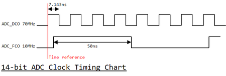
Today I modified the ADC_FCO period in the sdc file for another need. I changed the period parameter from 100 to 28.572. It is just two times to the period of the ADC_DCO clock (14.286), with a pico-second unit.
create_clock -name ADC_DCO -period 14.286 -waveform {0 7.143} [get_ports {ADC_DCO ADC_DCO(n)}]
create_clock -name ADC_FCO -period 28.572 -waveform {3.571 17.857} [get_ports {ADC_FCO ADC_FCO(n)}]
Then what I expected for a long time occurred. The edge of the ADC_FCO is located 3.571 ns away from the ADC_DCO edge. Here it is!
Is it a point to write period time multiplied by an integer instead of actual period one, with a pico-second unit?
Setup
Hold
Regards,
HKana17
- HKana172 years ago
Hi.
I modified the period time to 100.002 (ps) in my ADC_FCO constraint like below.create_clock -name ADC_FCO -period 100.002 -waveform {3.571 53.571} [get_ports {ADC_FCO ADC_FCO(n)}]
The clock frequency of ADC_FCO is just 10.000MHz. So the real period is 100.000ns. 100.002 is the number multiplied by 7 of the ADC_DCO period (14.286).Is this the trick here? Where can I see this in Intel's (Altera's) documents?
Regards,
HKana17
- HKana172 years ago
Excuse me. I forgot to write an important thing.
I succeeded it with the 100.002's clock constraint.


