Forum Discussion

 Occasional Contributor
Constraint for phase-shifted external clock (Specifying Clock Waveform Edges)
- 2 years ago
After looking at the Board Configuration, I believe this is Source-Synchronous Interface.
You may refer to the AN 433: Constraining and Analyzing Source-Synchronous Interfaces, section "Input Clock Constraints" on how to constraint the clock.
With the current clock constraints you have, they are not synchronous with each other. Therefore, meeting either the phase-shift or frequency requirement cannot fulfill both requirements simultaneously.
One approach I can suggest is to write a clock constraint in such a way that Quartus treats this as a PLL, ensuring that both clocks are synchronous with each other.
Regards,
Richard Tan


 Super Contributor
Like I said, you're using decimal frequencies/phase shifts that are not exactly multiples of each other in your constraints. Why can't they be:
create_clock -name ADC_DCO -period 14.286 -waveform {0 7.142} [get_ports {ADC_DCO ADC_DCO(n)}]
create_clock -name ADC_FCO -period 100 -waveform {3.571 53.571} [get_ports {ADC_FCO ADC_FCO(n)}]
Better yet, input one clock and use a PLL to generate the 2 synchronous clocks if you can.
These are very odd frequencies and phase shifts to rely on just what is arriving at the device.
 Occasional Contributor
Thank you for your reply.
Do you mean to rewrite 7.143 to 7.142? The waveform option affects its duty cycle and phase. The frequency is defined by the period option. The ratio 100ns to 14.286ns is almost 7-- 6.99986. Am I wrong? Here, I supposed that the length of traces from the ADC to MAX10 is the same.
In my case, the PLL exists in the external ADC. Here is the block diagram of the ADC.
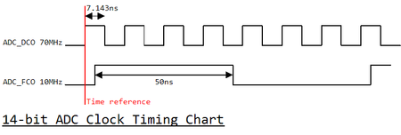
The PLL generates the data clock (ADC_DCO) multiplied by 7 times the input clock. The frequency of the frame clock (ADC_FCO) is the same as the input clock and phase-shifted precisely to ADC_DCO. Here is the timing chart. (But in my board, because of the miss of the board trace DCO polarization is inverted.)
Again how can I write a constraint for this configuration?
Regards,
HKana17


