Forum Discussion

 New Contributor
DK-DEV-AGI027-RA: JTAG chain broken after Nios V Hello, FPGA recovery fails
Hello,
I am using the following board and host environment:
- Board: Agilex 7 FPGA I-Series Development Kit, DK-DEV-AGI027-RA
- Serial number: 8100604
- Quartus Prime Pro: 25.3.1
- Host OS: Windows 11 Pro
Before this issue, the board was working normally with CXL ED and PCIe designs.
Issue summary
After successfully running a modified version of the "Nios V Hello" tutorial design (SOF + ELF) on this kit, Quartus Programmer can no longer detect the JTAG chain reliably. "Auto Detect" fails, and the JTAG Chain Debugger reports unknown devices and possible JTAG signal issues.
Steps and observations
1. I modified the Nios V Hello tutorial design (SOF + ELF), including pin assignments and power management & SmartVID assignments, to match DK-DEV-AGI027-RA. Programming completed successfully, and I confirmed the expected "Hello" output.
After that first run, I attempted to download an updated SOF, but Quartus Programmer "Auto Detect" failed.
JTAG Chain Debugger screenshot:
Programmer/Debugger log:
!Error: JTAG chain problem detected
!Error: TDI connection to the first detected device UNKNOWN_00000001 might be shorted to GND
!Error: The TCK and TMS connections to the device before the first detected device UNKNOWN_00000001 might have a problem
!Info: Detected 2 device(s)
!Info: Device 1: UNKNOWN_00000001
!Info: Device 2: UNKNOWN_020D10DD
Recovery attempts and results
2. Connected an external USB-Blaster II to J10, set SW8.3 = ON, and completed MAX10 recovery successfully.
3. Set SW8.3 = OFF to attempt FPGA recovery. Quartus Programmer Auto Detect still failed.
4. Loaded the predefined fpga_recovery.cdf and attempted to program AVSTX8.pof, but it failed with:
Error(209062): Flash Loader IP not loaded on device 2
Error(209012): Operation failed
5. Set SW8.2 = ON to remove the FPGA from the JTAG chain, then successfully programmed AVSTX8.pof into QSPI.
6. Set SW8.2 = OFF again, but Auto Detect still failed.
7. Removed the external USB-Blaster II and tried the embedded JTAG interface. Auto Detect still failed.
Questions.
- Are there additional recommended steps beyond MAX10 recovery and programming the recovery POF to QSPI (for example, specific switch combinations, a required full power-cycle sequence, or other board-level recovery steps)?
- If MAX10 recovery completes but JTAG remains broken on both external and embedded JTAG, does this suggest a likely hardware issue (JTAG path, FPGA, or related circuitry) that requires RMA?
- Is there anything in the Nios V Hello tutorial flow that could plausibly cause this condition (for example, power management settings, pin assignments, or JTAG-related settings)?
If needed, I can share additional logs, exact switch settings, and any other diagnostics you recommend.
Thanks.
13 Replies
 SteveK_Arrow
Hi
What happens if you power cycle the board after you get the JTAG chain problem notification? Can you scan the JTAG chain successfully?
 NIJGNAS
Hi SteveK_Arrow,
I tested that. After the JTAG chain problem occurred, I power-cycled the board and tried scanning again.
Result: no change. JTAG Auto Detect still fails after the power cycle on both:
- embedded JTAG, and
- external USB-Blaster II via J10.
The JTAG Chain Debugger continues to show the same behavior (unknown devices, chain problem) as before. 'jtagconfig --debug' shows the same.
Thanks.
- SteveK_Arrow
Hi NIJGNAS
Is the QSPI device flashed with content? What are the MSEL DIP switch SW2[1:4] settings? Are they set to configure using JTAG or Avalon streaming interface x8?
Thanks
- SteveK_Arrow
Hi
Can you provide more details regarding the Nios V Hello tutorial modifications, including the SmartVID changes? The issue seems to imply that either the FPGA was damaged or is not being powered to its required core voltage.
Thanks
- NIJGNAS
Hi,
Sure. I followed the DK-DEV-AGI027-RA dev kit documentation and only changed the configuration scheme, SmartVID (PMBus) related settings, and the clock/reset pin constraints when porting the Nios V Hello design.
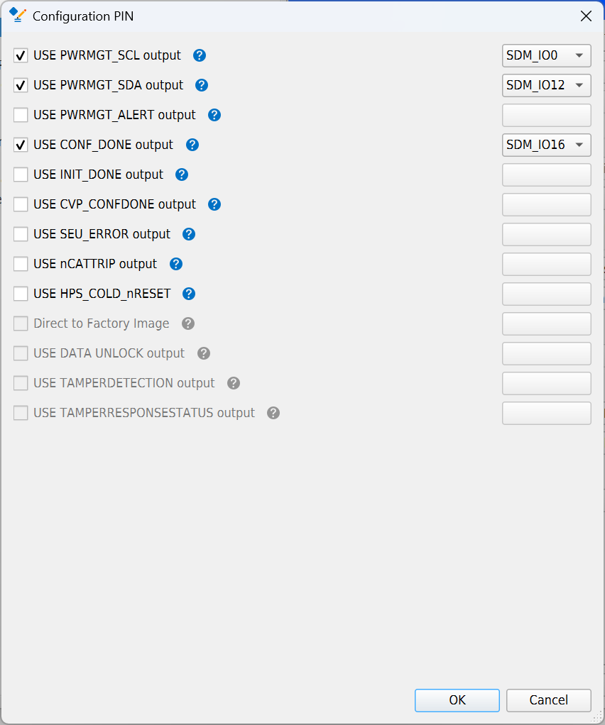
I am attaching screenshots of:
- Device and Pin Options - Configuration
- Configuration Pin Options
- Device and Pin Options - Power Management and VID
1) Device and Pin Options settings
Section Setting Value Configuration Configuration scheme AVST x8 Configuration VID mode of operation PMBus Master Configuration Pin Options USE PWRMGT_SCL output Enabled, SDM_IO0 Configuration Pin Options USE PWRMGT_SDA output Enabled, SDM_IO12 Configuration Pin Options USE CONF_DONE output Enabled, SDM_IO16 Configuration Pin Options Other pins (PWRMGT_ALERT, INIT_DONE, etc.) Not enabled Power Management and VID Bus speed mode 100 KHz Power Management and VID Slave device type Other Power Management and VID Number of slave devices 1 Power Management and VID PMBus device 0 slave address 47 Power Management and VID Enable PAGE command Off (unchecked) 2) Clock and reset constraints used
# Reset
set_location_assignment PIN_D36 -to reset_reset_n
set_instance_assignment -name IO_STANDARD "1.2-V" -to reset_reset_n
# Clock (differential)
set_location_assignment PIN_N45 -to clk_clk
set_location_assignment PIN_L46 -to clk_clk(n)
set_instance_assignment -name IO_STANDARD "True Differential Signaling" -to clk_clk
These settings allowed the design to program successfully and print the "Hello" message once. After that first run, JTAG Auto Detect started failing with the UNKNOWN devices and the same JTAG chain error messages as previously posted.
Thanks.
- SteveK_Arrow
Hi
I think it would be interesting to see what happens if the SDM I2C controller is disabled. The SDM controller is responsible for the SmartVID function and the JTAG chain.
Set SW4 [1:4] to OFF/OFF/ON/OFF, where OFF is open and ON is closed. (Table 4 of the Development Kit User Guide)
Thanks
- NIJGNAS
 BoonBengT_Altera
Moderator
Hi NIJGNAS ,
I hope you’re doing well. I wanted to follow up and check if there are any remaining questions or concerns regarding this matter.
Please let us know if anything still needs clarification — we’re happy to assist further.
Thank you for your time, and we look forward to your feedback.
Best Wishes
BB
 RaduB_Altera
Occasional Contributor
There may be a problem with the voltage regulators on that board. We are working on it, and will get back here when we have a solution. Thank you!