Ok so I have determined that the busy signal is not high before sending the commands.
My problem now though is that I cannot seem to be able to read and write to the epcq. my current steps are to enable 4 byte addressing then write an 8 bit number to the first register of the epcq (H'00000000) then read that number back to make sure I know how to do it before I start doing more but even this is proving to be challenging. I'm including my code and a screenshot of signal tap. Can somebody tell me if I am doing this right. I feel like its pretty straightforward on the datasheet but I just can't seem to get it to work.
Also this is the board I am using here:
http://www.terasic.com.tw/cgi-bin/page/archive.pl?language=english&categoryno=167&no=816 module battery_power_on_timer(
input wire clk_5MHz,
input wire reset_n,
// ASMI Interface inputs
input wire asmi_busy,
input wire data_in,
input wire data_valid,
input wire illegal_write,
// input wire rdid_in,
input wire read_address_in,
input wire status_in,
// Battery Powered INPUTS
input wire on_battery_power,
// Battery On Time Interface
output wire battery_on_out,
// ASMI Interface outputs
output reg addr_out,
output reg data_out,
output reg en4b_addr,
output reg ex4b_addr,
output reg rden,
output reg read,
output reg read_status,
output reg sector_protect,
output reg wren,
output reg write
);
// Registers here
reg state;
reg data_out_reg;
reg stage, stage1, stage2;
// State Machine Parameter Defination
parameter enable_4baddr = 8'b00000000;
parameter writing = 8'b00000001;
parameter reading = 8'b00000010;
parameter wait_1 = 8'b00000100;
parameter wait_2 = 8'b00001000;
parameter wait_3 = 8'b00010000;
parameter stop_it = 8'b00100000;
// Other Parameters
parameter time_record_address = 32'h00000000;
initial begin
state <= enable_4baddr;
addr_out <= time_record_address;
data_out <= 8'b00000011;
end
//main module
always @(posedge clk_5MHz, negedge reset_n)
begin
if(reset_n == 0)
begin // Reset everything
state <= 0;
end
else
begin
if(on_battery_power == 1) begin
if (state == enable_4baddr) begin
if(asmi_busy == 0) begin
if(stage == 0) begin
wren <= 1;
en4b_addr <= 1;
stage <= 1;
end
else begin
wren <= 0;
en4b_addr <= 0;
stage <= 0;
state <= wait_1; // wait two clock cycles before issuing new command
end
end
end
if (state == wait_1)begin
if(stage == 0)begin
stage <= 1;
end
else begin
state <= writing;
stage <= 0;
end
end
if(state == writing) begin
addr_out <= time_record_address;
if(asmi_busy == 0) begin
if(stage1 == 0) begin
wren <= 1;
write <= 1;
stage1 <= 1;
end
else begin
wren <= 0;
write <= 0;
stage1 <= 0;
state <= wait_2; // wait two clock cycles before issuing new command
end
end
end
if (state == wait_2)begin
if(stage == 0)begin
stage <= 1;
end
else begin
state <= reading;
stage <= 0;
end
end
if(state == reading) begin
if(asmi_busy == 0) begin
if(stage2 == 0) begin
read <= 1;
rden <= 1;
stage2 <= 1;
data_out_reg <= data_in;
end
else begin
read <= 0;
rden <= 0;
stage2 <= 0;
state <= stop_it;
end
end
end
end
else begin// else battery power off
end
end
end
endmodule
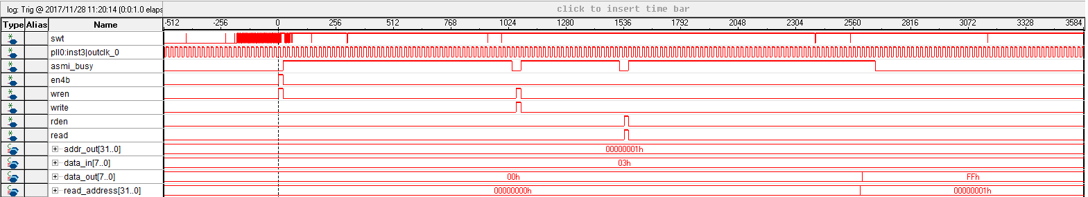
Here are the results:
I first enable 4 byte addressing then write to the epcq then try to read from it. addr_out is the address I'm reading/writing to. data in is the random 8 bit number I'm writing to the epcq and data_out is where I am expecting to see the same number after I read; however, I only ever see FFh as an output on data_out instead of 03h as I would expect. I know that the read command hasn't finished in this screenshot but know that data_out does not change when the read command is done. (I was having a hard time fitting everything in the signal tap window.) the read_address shows the address that is being read from and this seems to be working fine.
any help is greatly appreaciated.
https://alteraforum.com/forum/attachment.php?attachmentid=14476&stc=1 Honored Contributor