Forum Discussion

 New Contributor
Global Clock & Regional clock inputs in Agilex M FPGA
Hi,
Kindly answer the following query related to USB PHY connection to MAX10 in Agilex I series FPGA design.
In the reference design, why USB phy is connected to BMC(MAX10) in PCIe based card based on Agilex I FPGA design.
What can be done using USB interface in the the design.
Regards,
Thulasi
7 Replies
 AqidAyman_Altera
Regular Contributor
Hi Thulasi,
Can you clarify if you are referring to Agilex M or Agilex I, as the title and the question you asked are in a different context?
Also, can you give me the link to the reference design you are referring to?
Regards,
Aqid Thulasi
Hi,
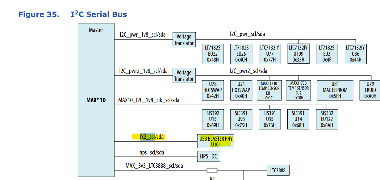
Please find the attached diagram based on Agilex M FPGA.
We want to know the function of USB interface in this board. Any document giving the details would be great.
- AqidAyman_Altera
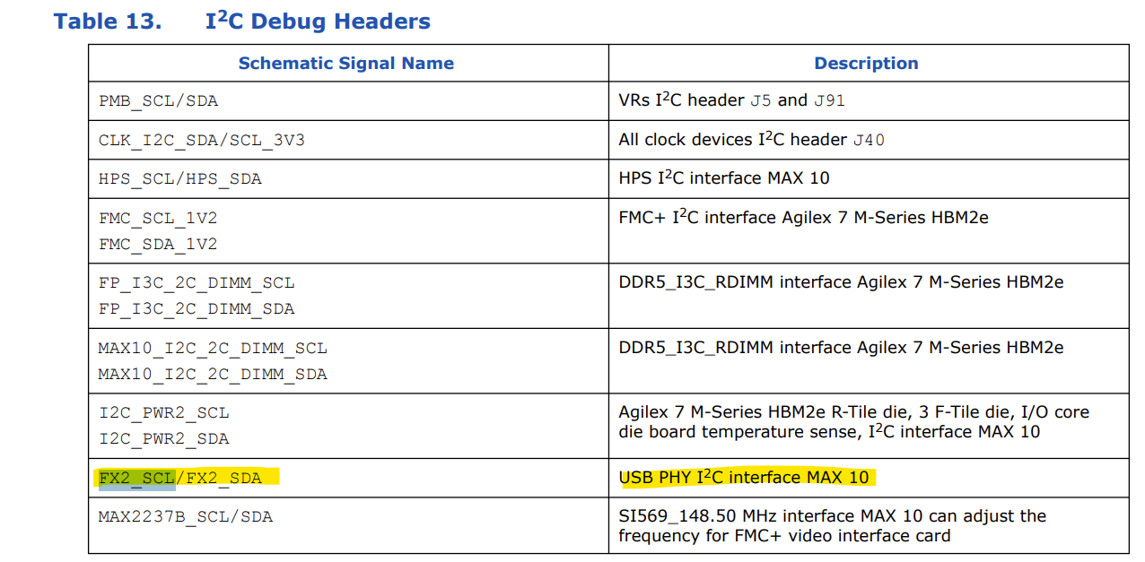
This is what I found in the Agilex 7 FPGA M-Series HBM2e Development Kit User Guide on the description of the signal connecting to this USB PHY.
Regards,


