Forum Discussion
 New Contributor
Cyclone V SoC GSRD precompiled SD boot failure
Hello all,
I have recently tried to execute the GSRD on the Cyclone V SoC (https://www.rocketboards.org/foswiki/Documentation/CycloneVSoCGSRD) , the first step is to boot a precompiled SD image.
I have downloaded the https://releases.rocketboards.org/2022.11/gsrd/c5_gsrd/sdimage.tar.gz and flashed an SD card as explained in the Windows chapter.
I than tried to boot the board.
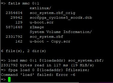
Seems like the load of the FPGA is failed in u-boot with the following error message: "Command 'load' failed: Error -6"
The u-boot then exists, kernel is starting and at some point the board resets and the boot sequence re-initiated.
I then removed the FPGA load lines in u-boot.scr, stopped manually in u-boot, flashed the FPGA via JTAG and continued to the kernel boot, It was successful and I had a running Linux prompt with a loaded FPGA.
when running the u-boot commands to load the FPGA:
load mmc 0:1 ${loadaddr} soc_system.rbf;
fpga load 0 ${loadaddr} $filesize;
the error messege "Command 'load' failed: Error -6" appears, even with other rbf files.
Since this is the precompiled SD image from Intel it seems like something is very strange
Also, in other SD images the FPGA load from u-boot was successful so I assume its not a board issue.
Has anyone experienced such issues?
Hello Aik,
After checking the pin configurations you provided - nothing actually booted --> No UART prints on putty of any kind.
Setting the following:
J26: Short pins 1-2
J27: Short pins 2-3
J28: Short pins 1-2
J29: Short pins 2-3
J30: Short pins 1-2And the rest as you instructed:
J5: Open
J6: Short
J7: Short
J9: Open
J13: Short
J16: OpenSW1: All OFF
SW2: All OFF (modified)
SW3: ON-OFF-ON-OFF-ON-ON (modified)
SW4: OFF-OFF-ON-ON (modified)I was able to successfully boot and load FPGA from u-boot.
6 Replies
 aikeu
aikeuRegular Contributor
- aikeu
Hi Shoval,
Can double check the bleow SW or MSEL jumpers settings are correct on the board?
First, the board jumpers need to be configured as follows:
J5: Open
J6: Short
J7: Short
J9: Open
J13: Short
J16: Open
J26: Short pins 2-3
J27: Short pins 2-3
J28: Short pins 2-3
J29: Short pins 2-3
J30: Short pins 2-3
J31: Short
Then, the board switches need to be configured as follows:
SW1: All OFF
SW2: All OFF
SW3: ON-OFF-ON-OFF-ON-ON
SW4: OFF-OFF-ON-ON
Thanks.
Regards,
Aik Eu
 Shoval
Hello Aik,
After checking the pin configurations you provided - nothing actually booted --> No UART prints on putty of any kind.
Setting the following:
J26: Short pins 1-2
J27: Short pins 2-3
J28: Short pins 1-2
J29: Short pins 2-3
J30: Short pins 1-2And the rest as you instructed:
J5: Open
J6: Short
J7: Short
J9: Open
J13: Short
J16: OpenSW1: All OFF
SW2: All OFF (modified)
SW3: ON-OFF-ON-OFF-ON-ON (modified)
SW4: OFF-OFF-ON-ON (modified)I was able to successfully boot and load FPGA from u-boot.
- Shoval
Hi Aik,
Setting the following:
J26: Short pins 2-3
J27: Short pins 2-3
J28: Short pins 2-3
J29: Short pins 2-3
J30: Short pins 2-3
Results in no load at all, not FPGA load and not u-boot/Linux boot, what I meant is that powering up the board using those configuration results in empty Putty with no prints at all.
The configuration that works for me - successfully boot and FPGA load is the following:
J26: Short pins 1-2
J27: Short pins 2-3
J28: Short pins 1-2
J29: Short pins 2-3
J30: Short pins 1-2J5: Open
J6: Short
J7: Short
J9: Open
J13: Short
J16: OpenSW1: All OFF
SW2: All OFF
SW3: ON-OFF-ON-OFF-ON-ON
SW4: OFF-OFF-ON-ON