Forum Discussion

 Occasional Contributor
Cyclone III slave (PS) embedded memory errors
 4 years ago
I think I've found the problem.
There is a trace connected to pin 76 on the master and pin 99 on the slave. Trace is pulled up to 3.3V via 2.2k
This **bleep** resistor was dead, and the trace was actually floating.
I didn't use this pins before, so I can't reveal the resistor is dead.
As I start to use it, all logic became a total mess. Something worked, something not. By elimination I found the culprit.
I can't explain how this trace connected with loading errors (when FPGA not even in user mode), but the fact is - replacing resistor solved all problems, ROMs working now (though I don't use them anymore).
Thanks to all, problem solved!
Occasional Contributor
@FvM wrote:
is the erroneous ROM content reproducible or arbitrarily varying? In the former case, I suspect a bug of the programming file conversion tool.
It's arbitrarily varying. Sometimes it's only one bit failed, sometimes it's 5-6. Sometimes bits are the same, but most of time they are varying.
The file conversion tool is ok, because, as I said, I can update ROM content through the In-system memory content editor (ISMCE) with the same file used in .sof/.pof, and then the content is ok.
@FvM wrote:
"If I try to reload slave via JTAG - there are errors." What does this exactly mean? You didn't show the JTAG configuration, are the devices configured in a chain? <> I presume you have separate .sof files for both devices?
It means that if I use JTAG to reload .sof file for slave, the ROMs content is still broken. And again, it's different bits are failing.
Yes, ofc, they are in JTAG chain. I have 2 different .sof files, and I can reload one or both devices.
So, here is an example what I'm doing:
1. Power up the board, both devices loads themselfs from EPCS (AS/PS). Master ROM is ok. Slave ROMs are failed.
2. Reloading slave via JTAG - still have ROM errors.
3. Reloading ROMs via ISMCE - ROMs are ok.
@FvM wrote:
How should the master/slave AS configuration affect JTAG operation?
Idk. I assume some ringing somewhere on the board, both DCLK/DATA0 and TCK/TDI/TDO.
But why the slave loads at all? If there is some error check, it should fail, isn't it? Or there is no error check?

 Super Contributor
Thanks for detailed explanation. Your conclusions are plausible, sounds like at least the memory initialization part of the configuration bit stream has insufficient consistency check.
Frank
P.S. According to my experience, double edges caused by ringing clock signal is the most popular signal integrity problem related to configuration. Series resistors providing source side termination can be essential to get clean clock.
- Vic3Dexe4 years ago
@FvM wrote:
Series resistors providing source side termination can be essential to get clean clock.
Thanks, but I've tried that already.
I've tried to remove buffers and change them to zero Ohm resistors - no changes.
Then I've replaced 0R resistors to 51R ones - no changes.
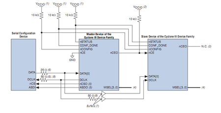
Then I've put buffers back, cut traces afters them (which are facing to the slave), and put 51R there in series. No changes.
Maybe it should'n be 51R, but smth bigger? Or smaller?
The situation is aggravated by the fact that I have nothing except soldering iron and multimeter )
I'm about to give up actually...


