--- Quote Start ---
we had the CDR set to LTD constant(is this bad?)
--- Quote End ---
Technically speaking, it would be impossible to set the CDR in this manner. The CDR can operate in AUTO or MANUAL mode. In AUTO mode, it starts out in LTR and then automatically transitions to LTD. In manual mode you have to implement the transition. The fact that you are not saying things like this makes me wonder if its not implemented quite correctly. (Note: that I'm saying this based on my recent tests with the S4GXDK, but I also did similar tests on the Cyclone IV GX Starter kit, so I'm pretty sure the same comments apply).
--- Quote Start ---
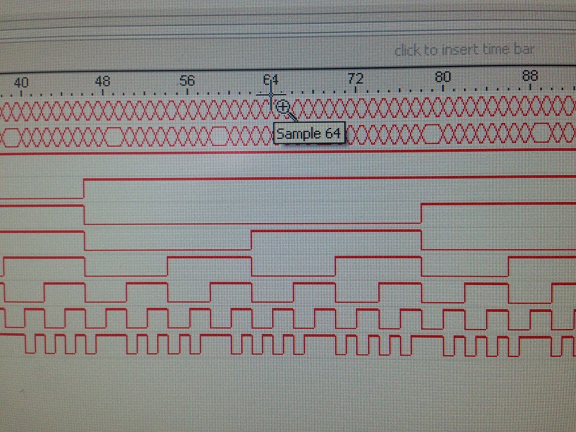
-we tried a loopback, my partner told me the data came in correct just shifted(the PMA and PCS layers of the transceiver are okay, which was what I was worried about).
--- Quote End ---
Ok, I assume this was the internal loopback option.
--- Quote Start ---
-we changed the capacitor to a lower value ( was 0.1uf, changed to 2nf)
-we tried numerous code methods (8b\10b, different word alignments, constant data, counters)
none of these worked, the strange loss of data is still there, but since the loopback proved the altgx fabric is fine (unless I'm wrong and it's not a reference to prove that.), we can assume this is still a physical issue.
something I'm worried about is the distance of the AC coupling capacitors from the FPGA, it's quite a long distance(see image) and I think this might be an issue for AC-coupled high data rates.
--- Quote End ---
Its probably not the location of the capacitors that is the issue, but perhaps the is the transition into those capacitors created by soldering them to the board per the photo you sent previously. Keep in mind that you've taken nice 100-Ohms differential traces and broken them out into wires "hanging in the breeze". While this works fine for frequencies up to a few 100MHz, its a bit sketchy at high frequency :)
Try a test where you reduce the data rate. If you have an oscilloscope that operates up to 1GHz or maybe 2GHz, try to drop the data rate so that you can look at the signals with an oscilloscope.
If you're at a university, then ask around and see who has nicer test equipment. I am sure you can ask someone to probe your board and show you what the signals look like at the pins of the FPGA.
That might yield a little insight as to your issue.
Cheers,
Dave
 Honored Contributor