Forum Discussion

 New Contributor
I would like to build a connection between my master device and max v, so I program an i2c interface logic to max v which I download from opencores. But I can read from my master device but can't write correctly to the MAX V cpld.
I would like to build a connection between my master device and max v, so I program an i2c interface logic to max v which I download from opencores. But I can read from my master device but can't write correctly to the MAX V cpld.
7 Replies
 EBERLAZARE_I_Intel
Regular Contributor
Hi,
Do you have the link to the documentation of the project from opencores?
Intel design store do have an example design implementing GPIO expansion using I2C bus interface on Max series if you want to check it out:
https://www.intel.com/content/dam/www/programmable/us/en/pdfs/literature/an/an494.pdf?GSA_pos=5&WT.oss_r=1&WT.oss=I2c+Protocol
 Zhilang_X_Intel
Hi el.ign,
Thanks for your reply! The link to the documentation of the project from opencores is https://github.com/mpDean9939/I2C-MasterSlave-Verilog.
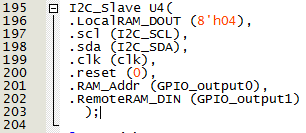
And I have tried the "an494 example design implementing GPIO expansion using I2C bus interface on Max series", it works well but it only have slave address matching and data while no register address. So I tried to modify it's .v file but it failed in connection between my master device and max v cpld. The situation is as I asked in intel forums, the link is https://forums.intel.com/s/question/0D50P00004Mh74YSAR/failure-of-modification-to-altera-example-an494-with-register-adddress. I also attach the modified verilog file and insert the image about the instance in the top module in this chat since there must be only one attachment, so the original .v file of an494 can't be attached, you can see it via the former link.
Please help me about my problem.
Best Regards,
Liam
- EBERLAZARE_I_Intel
Hi Liam,
Great that the example design did work, I noticed that the example design an494 demonstrate no register address, we do have another example design that have command register:
https://www.intel.com/content/dam/www/programmable/us/en/pdfs/literature/an/an486.pdf
However this example design demonstrate the MAX FPGA devices serve as a bridge between a host that has serial peripheral interface (SPI) to communicate with devices connected through an I2C bus. This may be as close as what you are trying to achieve.
Regards.
- Zhilang_X_Intel
Thanks for your advice. But the an486 example set the MAX FPGA to a master not a slave, and I just set my MAX V to a I2C slave. So could you please help me review my I2C_to_GPIO_modify file?
- EBERLAZARE_I_Intel
Hi,
Are you facing the write issue using the code entirely from opencores? I am unsure if the code are supposedly targeted for MAX V device.
I am not really familiar with verilog, but you probably want to get the register address code to work first since the an494 example is already working.
Regards.