Forum Discussion

 Occasional Contributor
error in ModelSim?
I am using Quartus II 64-Bit Version 13.0.1 to change a design for a MAX3000a series chip and I want to simulate it with ModelSim-Altera which is contained in the Quartus II software.
Simulation for MAX3000a series is not possible because the file max3000a_ver is not available. Therefore I changed the device type to MAX V, and simulation is possible.
Before changing the design I wanted to simulate the original design working successfully in hardware. But the simulation result is wrong. To show the effect see the attached files.
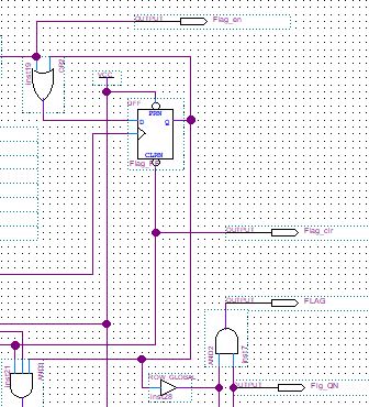
In schematic_part.jpg a small part around a flipflop is shown. The waveforms simulation results are shown in waveforms_part.jpg.
Every time when Flag_en is high during the positive edge of CLK the Q output of the flipflop shall be set high and can be reset by a low pulse of Flag_clr. As long as Flg_QN is high FLAG has the same level as Q.
The simulation result shows FLAG low all the time inspite of positive edges of CLK during Flag_en pulses.
I found images of simulation results from the original design where every Flag_en pulse resulted in a FLAG pulse which then was reset by a Flag_clr low pulse, i.e. formerly ModelSim-Altera showed the expected result.
Is there a setting for ModelSim I overlooked to get it working correctly?
Hi,
Inside the testbench myProject_tb_1.v, make sure the module name also myProject_tb_1.
Thanks,
Regards,
Sheng
15 Replies
 ShengN_altera
Super Contributor
Hi,
University Program VWF Simulations is legacy simulator. Probably some of the IP upgradation is not included in this legacy simulator. I would suggest to use the modelsim or questasim simulator.
Thanks,
Regards,
Sheng
 Niko3
Niko3Hi,
I chose University Program VWF because I'm not familiar with VHDL to write a testbench and because VWF provides a simple interactive method to generate waveforms. The single bits of a bus can be grouped and then a value can be defined for the group.
I had a look at modelsim and are missing a simple method to generate waveforms for buses. The design contains some 4bit buses as input which have to be defined for a testbench. The only graphical way (edit -> create/modify waveform -> ...) to generate waveforms I found is to define every single bit of the buses which is very tedious.
Do you know a better method?
- ShengN_altera
Hi,
You may try this method create testbench using modelsim-altera wave editor https://www.intel.com/content/dam/support/us/en/programmable/kdb/rd11032011-561/creating-testbench-using-modelsim-altera.pdf
The only graphical way (edit -> create/modify waveform -> ...) to generate waveforms I found is to define every single bit of the buses which is very tedious
Do you mean University Program VWF? I would suggest you to use modelsim-altera as University Program VWF has a lot of limitations
Thanks,
Regards,
Sheng
- ShengN_altera
Hi,
May I know do you have any further concern?
Thanks,
Regards,
Sheng
- Niko3
Hi,
I made a lot of tests and found step by step a nearby solution.
The actual status:
- testbench creation successful (hopefully)
- simulation with modelsim-altera starts and shows some waveforms
- problem1: in the wave display all input signals defined in the testbench are HiZ
- problem2: simulation stops at 25ns but the testbench contains data until 2000ns
Do you have an idea what is wrong?
Thanks Niko3
- ShengN_altera
Hi,
Possible provide design for taking a look?
Thanks,
Regards,
Sheng
- Niko3
Hi,
my design is a schematic, i.e. a .bdf file. There are many files generated by Quartus II software and modelsim.
what do you need?
- ShengN_altera
Hi,
Could you archive the project in a .qar file and provide to me?
Thanks,
Regards,
Sheng
- Niko3
Hi,
attached all files of my project in a tar file.
After defining the input data in the wave editor I exported the testbench (myProject_tb) according to the document
"Creating Testbench using ModelSim-Altera Wave Editor".
Then I defined the testbench within Quartus II according to the document
"Simulating in ModelSim-Altera Edition using NativeLink".
Then I called modelsim from Quartus II (Tools / Run Simulation Tool / Gate Level Simulation...). But, as reported, in the wave window all inputs were HiZ and simulation stopped at 24 ns.
Meanwhile problems got more:
I was fighting with the sequence of names in the wave window. Initially they were sorted totally mixed up. Now I achieved a reasonable functionally grouped sequence by editing the file wave.do. After these editings calling modelsim I get the following error.
# ** Error: (vsim-3170) Could not find 'H:/Arduino/Quartus-Projekte/myProject/simulation/modelsim/gate_work.myProjekt'.
#
# Error loading design
Hopefully you can give me some tipps how to get the simulation running.
Thank you for your effort.
- ShengN_altera
Hi,
You can include .vo file in Project Navigator -> Files.
Go to Assignments -> Settings -> EDA Tool Settings -> Simulation and make sure the the testbench name correct which is myProject_tb instead of myProjekt_tb.
Then run compilation and go to Tool -> Run Simulation Tool -> Gate Level Simulation
Attached the design and result i got below.
Thanks,
Regards,
Sheng
- Niko3
Hi,
thank you very much. What a stupid error!
A final question: modelsim displays the signals in a fuzzy sequence. Where is the best location to reorder the sequence of signals in a functionally reasonable sequence?
- ShengN_altera
Hi,
You may re-arrange the sequence of the wire and reg in myProject_tb.v
Thanks,
Regards,
Sheng
- Niko3
Hi,
I'm here again with a new problem, sorry.
I wanted to generate several test benches. So, I started again with the wave editor.
- in modelsim deleted wave window
- with text editor modified in wave.do the lines "wave modify ..." for the inputs DI0 ... DI3 to get new input data
- in modelsim loaded the modified wave.do: File / Load / Macro File...
- in modelsim exported the new testbench: File / Export / Waveform... with the new name myProject_tb_1
- closed modelsim
- in Quartus II changed testbench: Assignments / Settings / Simulation / click on Test Benches...
then deleted old test bench "myProject_tb"
added new test bench "myProject_tb_1"
7. started modelsim: Tools / Run Simulation Tool / Gate Level Simulation...
error deleting "msim_transcript": permission denied
8. closed Quartus II and modelsim
9. deleted msim_transcript
10. started Quartus II
11. started modelsim: Tools / Run Simulation Tool / Gate Level Simulation...
# ** Error: (vsim-3170) Could not find 'H:/Arduino/Quartus-Projekte/myProject/simulation/modelsim/gate_work.myProject_tb_1'.
#
# Error loading design12. opened myProject_tb_1.v with text editor and saw that it contained only a few lines
13. deleted test bench in Quartus II
14. repeated steps 1 -- 5
15. now myProject_tb_1.v was ok
16. in Quaartus II added test bench myProject_tb_1
17. started modelsim: Tools / Run Simulation Tool / Gate Level Simulation...
same error as in step 11
Is'nt it possible to use several different test benches and if yes how to do it?
- ShengN_altera
Hi,
Inside the testbench myProject_tb_1.v, make sure the module name also myProject_tb_1.
Thanks,
Regards,
Sheng
- Niko3
Hi,
From your hint I compared my successful test bench myProject_tb.v with myProject_tb_1.v and found following difference:
myProject_tb.v: module myProject_tb ;
myProject_tb_1.v: \module myProject_tb_1.v ;
After editing in myProject_tb_1.v: \module myProject_tb_1.v to module myProject_tb_1
and compiling again it works
It is essential that after changing the name of the test bench the design shall be compiled!
Nevertheless, I find it astonishing that modelsim generated a faulty myProject_tb_1.v. Well, now I will check every new test bench file.
Thank you very much. I appreciate your excellent support.
With best regards
Niko3