quality|reliability
64 Topics
Introducing the Altera Community AI Responder — Beta
Altera is introducing the AI Responder, an assistant built into the Altera Community to help provide faster, context-aware guidance for Altera product questions. It uses relevant public Altera documentation and Knowledge Database content, with coverage continuing to expand. The AI Responder may provide source references and can hand off complex or out-of-scope questions to an Altera subject-matter expert. As a beta feature, responses may contain errors or omissions, so please review the sources and verify technical guidance against official Altera documentation before implementation. If the response does not fully address your question, add more context and tag ai_responder to continue the discussion. We welcome your feedback as we improve the Community experience.27Views0likes0Comments
Quartus Programmer 21.1: JTAG Server Error Code 82 – Port 1309 Cannot Be Bound
Hello Altera Community, I am working on an FPGA project using a Cyclone IV FPGA development board and an Altera USB-Blaster. I am currently unable to program the FPGA because Quartus Programmer cannot access the JTAG server. System details: - OS: Windows 11 64-bit - Software: Quartus Programmer 21.1 - Installation path: C:\intelFPGA\21.1\qprogrammer - Programmer: Altera USB-Blaster - FPGA: Cyclone IV development board The USB-Blaster is detected by Windows Device Manager and the driver is installed. The USB-Blaster also powers on normally. However, Quartus Programmer gives: "Attempted to access JTAG server -- internal error code 82 occurred" When I run: jtagconfig I get: Error when scanning hardware - Server error Sometimes it also hangs at: Connecting to server(s) [...] I checked the JTAG server using: jtagserver --status It reports: Installed JTAG server is 'C:\intelFPGA\21.1\qprogrammer\bin64\jtagserver.exe' Server is stopped Remote clients are disabled I tried reinstalling the JTAG server: jtagserver --install jtagserver --start But the server immediately stops. I also tried: net start "Altera JTAG Server" The result was: The Altera JTAG Server service could not be started. The service did not report an error. NET HELPMSG 3534. I then ran: jtagserver.exe --foreground and received: Unable to bind changedetect socket: 10048 Can't bind to TCP port 1309 - exiting I checked the port using: netstat -ano | findstr 1309 and found that TCP port 1309 was being used/listened to by another process, for example PID 12888. I tried terminating the process using: taskkill /F /PID 12888 but Windows reported: ERROR: The process with PID 12888 could not be terminated. Reason: There is no running instance of the task. I also tried stopping the JTAG server, reinstalling it, and restarting it. In addition, I already tried the following: 1. Disabled PCI Express → Link State Power Management. 2. Disabled USB Root Hub power saving ("Allow the computer to turn off this device to save power"). 3. Stopped the Print Spooler service. 4. Closed Quartus/Programmer-related applications. 5. Reinstalled the JTAG Server. 6. Restarted the computer. 7. Tried starting the JTAG server manually. 8. Checked TCP port 1309 using netstat. The problem still remains. My main questions are: 1. Why is Quartus Programmer 21.1 unable to start the JTAG Server? 2. What is causing TCP port 1309 to remain occupied? 3. Is there a known issue with Quartus Programmer 21.1 and Windows 11? 4. Is there a recommended patch, driver, or newer Quartus Programmer version for this problem? 5. Is it possible to configure the JTAG server to use another TCP port? 6. What is the correct way to completely remove and reinstall the JTAG Server on Windows 11? 7. Is there anything else I should check before reinstalling Quartus Programmer? I would appreciate any guidance on how to get the JTAG Server running so that jtagconfig can detect my USB-Blaster and FPGA. Thank you.260Views0likes5Comments
There are distinct scratches on the BGA substrate, extending beneath the solder balls.
I would like to ask a question. There is an issue with this BGA product, model number EP4CE30F23C8N: there are scratches on the bottom substrate that have penetrated the solder balls. Could this be a quality issue? I would be grateful if you could provide a reply. Many thanks! I have attached the image,Thank you.556Views0likes5Comments
Updated .brd file for Stratix 10 GX dev kit
Referencing this post: EK-10M08E144 PCB .brd file corrupted | Altera Community - 302242 The .brd file that comes in the documentation at: https://www.altera.com/products/devkit/po-3028/stratix-10-gx-signal-integrity-development-kit-h-tile ...was done in Allegro, prior to version 16.6. The only available Allegro viewer gives an error because it was done prior to version 16.6, and you need the DB Doctor utility to update the file. The only way to get the DB Doctor utility is to install Allegro. If I had Allegro...I would not be installing the Allegro viewer. Altera: As mentioned in the post above (well over a year ago), it would make sense for you to update your files so customers can view the board of their $10K+ development board. How do we make that happen? Thanks!528Views0likes4Comments
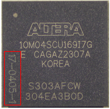
vertical side marking on MAX10 UBGA169 package?
Dear All, can somebody help me with side marking on this 10M04SCU169I7G? the one with inscription is DC2023, the one without DC2020 i believe. Not sure if its customer specific? Trace info idk.. UBGA169 package Thank you so much in advance156Views0likes5CommentsFunctional fail and suspect relate to the component
Hi Altera team, I found a problem for the functional fail issue after mount the FPGA on the boards and teste. After replace the new part the functional is gone and passed our functional test criteria. The log file is the confidential data and I would like to request for Private Message support. Thank you.180Views0likes3Comments
Unable to Generate Valid PAM4 Eye Diagram and BER Measurements on Stratix 10 SI E-Tile Native PHY
Hardware Intel Stratix 10 Development Kit E-Tile Native PHY IP Single SMA TX and RX channel SMA-to-SMA cable (50 Ω) Software Quartus Prime Pro 18.1 Intel Transceiver Toolkit Configuration PAM4 operation Line rate: 51 Gbps One TX channel connected directly to one RX channel through an SMA cable Design compiles successfully and programming is successful. Problems Encountered 1. PAM4 Eye Detection Failure Transceiver Toolkit reports: "PAM4 eye could not be detected, check lock status and run RX adaptation." 2. RX Adaptation Questions One-time adaptation completes successfully, but: Eye detection still fails. BER measurements do not produce a usable eye diagram. Questions: Should continuous adaptation be used instead? Is there a recommended adaptation sequence before running Eye Viewer? 3. Eye Diagram Parameters Undefined After running Eye Viewer: Eye Width = Undefined Eye Height = Undefined i.e. ratio = (0/0) The heatmap returns with full RED and no eye diagram. The eye diagram is not generated even though the receiver reports lock. 4. BER Test Issues I am unsure: How many bits are required before Eye Viewer can successfully generate a PAM4 heat map. Whether there is a minimum BER sample count required for a valid eye diagram at 51 Gbps. Whether insufficient captured bits can cause "Undefined" eye width/height. 5. TX Pattern Currently transmitting a repeating user-defined pattern, for example: .tx_parallel_data({20{40'b0, 40'h0F0F0F0F0F, 40'b0, 40'h0F0F0F0F0F}}) Questions: Is this pattern suitable for PAM4 eye measurements? Would PRBS13 or PRBS31 be required instead? 6. Signal Integrity Questions: Can a 50 cm SMA cable (Pasterneck PE3CA1035) reliably carry a 51 Gbps PAM4 signal? Is additional equalization or TX pre-emphasis typically required even for short SMA connections? 7. Transceiver Toolkit Configuration I would appreciate guidance on: Recommended Eye Viewer settings. Auto Sweep configuration. Vertical and horizontal ranges. TX FIR tap values. RX CTLE/DFE settings. Required number of bits before starting the eye scan. What are the common reasons for "PAM4 eye could not be detected" despite PLL/CDR lock? What checks should be performed before running Eye Viewer? PRBS as well as USER sequence, both generate complete RED heatmap, why? How many bits should be accumulated before generating an eye diagram at 51 Gbps? Are there recommended TX FIR, CTLE, and DFE settings for a direct SMA-to-SMA connection? Has anyone successfully generated a PAM4 eye using the Stratix 10 E-Tile Native PHY over SMA? If so, could you share the required configuration or debugging steps?Solved1KViews0likes8CommentsMAX10 for 5V LVTTL interface
I want to understand from the learned user that can I use MAX10 in below mentioned scenario... MAX10 is configured as OD 3.3 LVTTL logic, with PCI clamp diode enabled. The IO pins are configured as bidirectional. The interface which is talking to MAX10 is a 5V LVTTL interface, but I have made sure that VIH, VOH, VIL and VOL are compatible. The VCCIO power pin is also supplied with 3.3 +/-1% voltage so that max clamp voltage at IO pad when PCI diode is active can reach max of 4.06V. I have also understood that during POR and configuration period HOT Socketing circuitry shall function to save IO pads on getting full 5V swing. Also, absolute max ratings recommend that if IO are getting max of 4.12V as 100% duty cycle, they can still continue to operate for more than 11 years. What I want to get confirm if this kind of operation has any drawbacks which I didn't considered, as Altera is nowhere saying the device can operate at 5V in any of their used case. This being unconventional approach I don't have any scenario to prove the risk-free working. Or if any one of you can point me to correct reference design /document82Views0likes1Comment