3rd party board
11 Topics
Workaround for TCK frq. limitations on USB-Blaster I/II/III & Clones (fixing "JTAG chain broken")
Workaround for TCK frequency limitations on USB-Blaster I/II/III and clones (fixing "JTAG chain broken") Hi everyone, I'd like to share a practical workaround for a problem many of us run into when programming Altera FPGAs through test fixtures, level shifters or long ribbon cables. **The problem** In these setups, "JTAG chain broken" or "Unable to scan device chain" errors are common. They are usually caused by signal reflections and poor termination on custom boards and long extensions. Lowering the TCK frequency is the standard remedy, but the options are limited: - USB-Blaster I (and most low-cost clones) runs at a fixed TCK of about 6 MHz. Quartus offers no way to change it. - USB-Blaster II can be set to 6/16/24 MHz via `jtagconfig --setparam <cable> JtagClock <freq>`, but nothing below 6 MHz. In practice this setting is also unreliable: it is not persistent and can fall back to the 24 MHz default (see Altera KB: "Why does the TCK frequency setting of the USB-Blaster II download cable revert to the default value of 24 MHz after being changed?"). In our experience it is a constant source of trouble, especially in production where it has to be set again and again. For really marginal lines, 6 MHz is often still too fast. **The workaround** Disclosure: I'm the developer of the tool described below, so please take this as information from the vendor. Quintus Programmer (by Dution) drives the JTAG lines of the USB-Blaster in bit-bang mode instead of using the adapter's fixed shift clock. This lets you choose the TCK frequency freely, e.g. down to 100 kHz, with the same USB-Blaster I/II/III or clones you already have. With a lower TCK, programming and verification become stable again on long or poorly terminated lines without any hardware changes. The standard USB-Blaster driver stays in place, and Quintus only replaces the programming step. **Before reaching for software, check the hardware basics** The recommendations from the Altera Knowledge Base still apply and often fix the problem on their own: - TCK pull-down 1 kΩ to GND, TMS/TDI pull-up 10 kΩ to VCCIO - a small capacitor (10–22 pF) at TCK near the FPGA against ringing edges - a TCK buffer on long or noisy lines If the layout can't be changed, a lower TCK is a practical way out. More info: search for "Quintus Programmer Dution". Happy to answer technical questions here.173Views0likes2Comments
Introducing the Altera Community AI Responder — Beta
Altera is introducing the AI Responder, an assistant built into the Altera Community to help provide faster, context-aware guidance for Altera product questions. It uses relevant public Altera documentation and Knowledge Database content, with coverage continuing to expand. The AI Responder may provide source references and can hand off complex or out-of-scope questions to an Altera subject-matter expert. As a beta feature, responses may contain errors or omissions, so please review the sources and verify technical guidance against official Altera documentation before implementation. If the response does not fully address your question, add more context and tag ai_responder to continue the discussion. We welcome your feedback as we improve the Community experience.22Views0likes0Comments 45Views0likes1Comment
Request for SmartVID PMBus Compatibility Requirements for Replacing VRM on Agilex 7
Dear Altera Support Team, We are designing a board using Agilex 7 AGMA032R47A1E2VC and currently plan to use Infineon XDPE19284C as the SmartVID voltage regulator. Due to cost and design complexity considerations, we are evaluating replacing the XDPE19284C with a TI solution, such as TPS546E25 (multi-device stack configuration). Our goal is to make the VRM replacement transparent to the Agilex SDM SmartVID function. In other words, after replacement, the Agilex device should operate normally without any changes in the SmartVID behavior. We understand that SmartVID communicates with the external VRM through PMBus, and that Agilex SDM does not depend on the internal VRM implementation (such as phase number). However, we would like to confirm all the required compatibility conditions. Could you please provide a complete checklist of the PMBus parameters and behaviors that must be identical between the original VRM and the replacement VRM? For example, we would like to confirm whether the following items are required to match: 1.PMBus slave address 2.VOUT_MODE (PMBus command 0x20) 3.Linear format exponent (N value) 4.VOUT_COMMAND format and scaling 5.READ_VOUT response format 6.OPERATION command behavior 7.STATUS_WORD / STATUS_BYTE behavior 8.PAGE command support and configuration 9.PMBus bus speed requirement 10.Any required Manufacturer Specific Commands (MFR_xxxx) 11.Any other SDM-specific PMBus transactions used during SmartVID initialization In particular, we would like to know: Does Agilex SDM SmartVID use only standard PMBus commands (such as VOUT_COMMAND, READ_VOUT, STATUS_WORD, OPERATION)? Does Agilex SDM access any VRM-specific Manufacturer Commands? Does Agilex identify or depend on the specific VRM model selected in Quartus? If the Quartus setting is configured as "Other" VRM, what exact requirements must the replacement regulator satisfy? Our understanding is that the most critical parameters for a Linear PMBus regulator are: PMBus address VOUT_MODE Linear format Linear exponent N VOUT_COMMAND interpretation However, we would like to confirm this with Altera before committing to a new PCB design. Could you please provide a detailed compatibility checklist or any internal guideline/documentation regarding SmartVID VRM replacement? Thank you very much for your support. Best regards,163Views0likes3CommentsIs it possible to attach PCIe to a Dev kit?
Hello Altera Community I have the DE25 Nano dev kit from Terasic. The Altera Agilex 5 product breif says the this FPGA has PCIe, but on the Dev kit this have not been installed. The pins for this should be exposed right? Is it possible that I could attach a PCIe component myself and how would that be possible? Thanks in advance.Solved67Views0likes1CommentAXC3000 Agilex 3 board
Hi, for a new design I'm starting to use an evaluation board from Arrow Electronics, (but designed by trenz electronics) with Agilex 3 https://github.com/ArrowElectronics/Agilex-3/wiki/Agilex-3-AXC3000-Development-Platform This board has an Hyperam W957D8NBRA4I installed but the Nios V example design uses only internal RAM. Anyone knows if the IP to use this ram is free into quartus or is necessary to acquire a license? Thanks263Views0likes6Comments
Arrow AXE5 Eagle Board JTAG issue
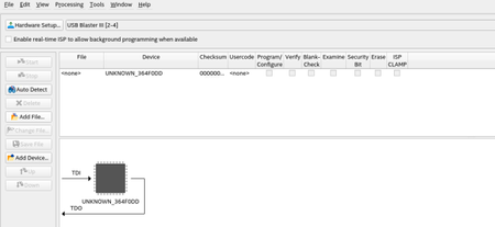
Hi, I have an AXE5 eagle board. The Quartus Programmer on Auto-Detect does show the usb blaster3 but the device is named UNKNOWN_364F0DD instead of A5ED065BB32AES4. What do you think could be the issue? BTW I am on Linux RHEL 8. I am using Arrow blaster and used FTProg to flash it as USB Blaster 3 as suggested by guide120Views0likes2CommentsPDN file and PCB decoupling
Hello, In the PDN excel file how is determined the ESR and ESL value for the decoupling capacitor ? I would like to add bigger capacitor . Is there some explanation for this file ? all the cells are locked. Is there some explanation to help to determine the number of capacitor needed for an application. I put the power rail voltage and current and now I need to determine the capacitor decoupling for each rail. I'm using a 5CEFA4_M13 chip on my board. Thanks for your help68Views0likes1Comment
EPM9320LI84-20
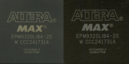
Hello! Could you please clarify something? Within the same batch of EPM9320LI84-20 FPGAs, the marking quality varies significantly, which is especially noticeable in the letter A in the ALTERA logo. This is not an isolated case within the batch—there are several chips with the same issue. Could this happen during manufacturing? As you understand, these chips were discontinued long ago and are no longer available from official distributors, so we have to source them from less reliable suppliers. Please respond as soon as possible. Thank you!160Views0likes4Comments