Altera_Forum Honored Contributor
11 years agoHonored ContributorWhy does the fitter generate a counter with a reversed bit order?
Hi All,
I am working on a controller for a 32x32 RGB matrix using the DE0 Nano. So far I have successfully manage to display a still image using a pair of 2-port RAM modules to store the top and bottom half of the display. The design uses three counters, one keeps track of the column data and LED on time, another keeps track of how many times the row is re-drawn to achieve an 8-bit resolution of brightness (24-bit colour) in a PWM fashion, and the final counter keeps track of the row. The counters are cascaded, starting with the column counter, then the PWM and finally the row counter: http://www.alteraforum.com/forum/attachment.php?attachmentid=10245&stc=1 The first two counters, 7-bit and 8-bit, are inferred by the fitter as expected. However the 4-bit row counter is inferred with a reversed bit order, as shown in the following screenshot: http://www.alteraforum.com/forum/attachment.php?attachmentid=10246&stc=1 The row counter needs to be connected to a physical 4-bit MUX on the 32x32 matrix. At the moment the design works fine if I connect the LSB of the MUX to the pin that joins the MSB of the row counter, i.e. in a reversed order, row_counter[0] to the D pin of the MUX and row_counter[3] to the A pin of the MUX. The codes for all the counters are very basic, and identical with the exception of the number of bits in each. Also the current code for the 4-bit counter has the carry flag removed, however this makes no difference to the bit order chosen by the fitter.module counter_4(
clk,
counter_out
);
input reg clk;
output reg counter_out = 0;
always @ (posedge clk) begin
counter_out <= counter_out + 1;
end
endmodule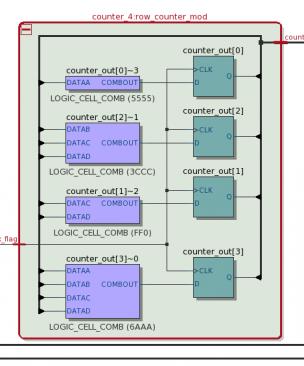