Altera_Forum Honored Contributor
15 years agoHonored ContributorHow to properly constrain data/strobe output?
Hi,
I have an FPGA driving an external register with data and clock signals. Both the data and the clock is generated through state machines in the FPGA (see attached simplified picture). I am trying to properly setup the TimeQuest constraints so that the setup and hold times of the exernal register is part part of the timing analysis. My understanding is that one should create a generated clock for the Stb output and then use set_output_delay -max and -min to cosntrain setup and hold times. I have run into difficulty creating the ganrated clock. I have tried the following: create_generated_clock -name Stb_clk -source Sys_Clk -divide_by 1 [get_ports {Stb}] When I update the timing netlist I get the following warnings / errors: Warning: Node: ...|HPIController:hpictrl|snHDS1 was determined to be a clock but was found without an associated clock assignment. Warning: No paths exist between clock target "pHPI_nHDS1" of clock "HpiStb_clk" and its clock source. Assuming zero source clock latency. (Note I have left the original names in the errors: snHDS1 is the name of the output of FF_Stb. It gets directly assigned - i.e no logic inbetween - to pHPI_nHDS1, which is the name of the port). The problem is that TimeQuest does not account fo the skew between the Sys_Clk and the Stb output pin. What I then did was to say: create_generated_clock -name Stb_clk_tmp -source Sys_Clk -divide_by 1 [get_pins {FF_Stb|q}] create_generated_clock -name Stb_clk -source Stb_clk_tmp -divide_by 1 [get_ports {Stb}] This seems to work and on first sight the setup / hold analysis seems right. But it does not feel right to create two clocks. Is there another way to do this? Am I doing something wrong? Regards, Niki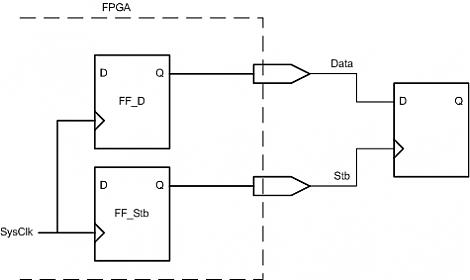