maya123 New Contributor
1 year agoNew ContributorAfter synthesis, I can't see the state diagrams in state machine viewer
Hi, everyone!
I'm using the OSPI protocol to transfer data from Cyclone IV to STM32.
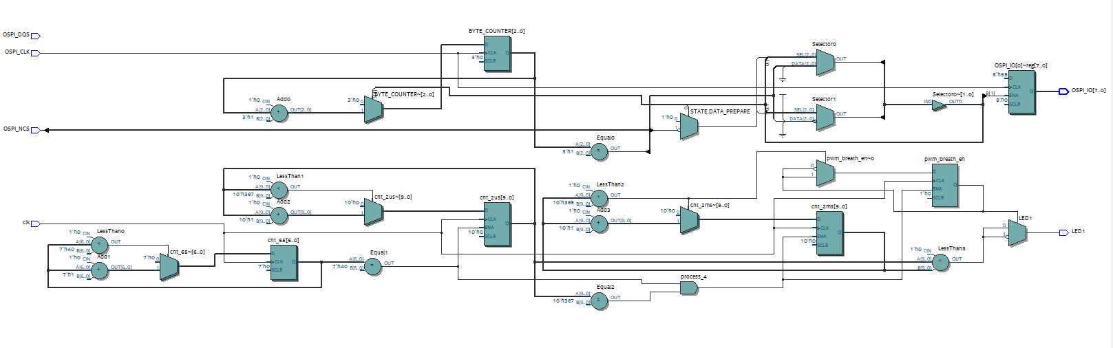
I designed a state machine with three states, and a piece of breathing light code that identifies the normal operation of the program. The code passed the synthesis, and the screenshot shows RTL, but there is nothing in the State machine viewer, it seems that my state machine has been optimized by Quartus.
LIBRARY IEEE;
USE IEEE.STD_LOGIC_1164.ALL;
USE IEEE.STD_LOGIC_UNSIGNED.ALL;
USE IEEE.NUMERIC_STD.ALL;
ENTITY OSPI_TEST_CONNECTION IS
PORT(
clk : IN STD_LOGIC; --- On-board crystal input,32.768Mhz
OSPI_CLK : IN STD_LOGIC; --- OSPI connection clock,input from stm32,8Mhz
OSPI_IO : OUT STD_LOGIC_VECTOR (7 DOWNTO 0); --- ospi_io
OSPI_NCS : IN STD_LOGIC;
OSPI_DQS : IN STD_LOGIC;
LED1 : OUT STD_LOGIC --- breath led
);
END OSPI_TEST_CONNECTION;
ARCHITECTURE BEHAVIOR OF OSPI_TEST_CONNECTION IS
--- state machine
TYPE STATE_TYPE IS (IDLE, DATA_PREPARE, DATA_TRANSMIT);
SIGNAL STATE : STATE_TYPE := IDLE;
SIGNAL DRDY : STD_LOGIC := '0'; --- DRAY:Data ready flags.
SIGNAL BYTE_COUNTER : INTEGER RANGE 0 TO 7 := 0; --- BYTE_COUNTER:Byte counter, plus 1 for each byte sent.
CONSTANT SEND_DATA : STD_LOGIC_VECTOR(7 DOWNTO 0) := "01010101";
SIGNAL OSPI_IO_TEMP : STD_LOGIC_VECTOR(7 DOWNTO 0);
--- PWM _breath _LED ---
SIGNAL cnt_65 : UNSIGNED(6 DOWNTO 0) := (OTHERS => '0');
SIGNAL cnt_2us : UNSIGNED(9 DOWNTO 0) := (OTHERS => '0');
SIGNAL cnt_2ms : UNSIGNED(9 DOWNTO 0) := (OTHERS => '0');
SIGNAL pwm_breath_en : STD_LOGIC := '1';
SIGNAL pwm : STD_LOGIC := '0';
CONSTANT T65 : UNSIGNED(6 DOWNTO 0) := TO_UNSIGNED(65, 7);
CONSTANT T2us : UNSIGNED(9 DOWNTO 0) := TO_UNSIGNED(1000, 10);
CONSTANT T2ms : UNSIGNED(9 DOWNTO 0) := TO_UNSIGNED(1000, 10);
BEGIN
PROCESS(clk,OSPI_NCS)
BEGIN
CASE STATE IS
WHEN IDLE =>
IF (OSPI_NCS = '0') THEN
STATE <= DATA_PREPARE;
ELSE
STATE <= IDLE;
END IF;
WHEN DATA_PREPARE =>
OSPI_IO_TEMP <= SEND_DATA;
DRDY <= '1'; --- data_ready ---
STATE <= DATA_TRANSMIT;
WHEN DATA_TRANSMIT =>
IF(DRDY = '1' AND BYTE_COUNTER = 1) THEN
STATE <= IDLE;
ELSE
STATE <= DATA_TRANSMIT;
END IF;
WHEN OTHERS =>
STATE <= IDLE;
END CASE;
END PROCESS;
PROCESS(OSPI_CLK)
BEGIN
IF RISING_EDGE(OSPI_CLK) THEN
IF (STATE = DATA_TRANSMIT AND DRDY = '1') THEN
OSPI_IO <= (OTHERS => '0');
OSPI_IO <= OSPI_IO_TEMP;
BYTE_COUNTER <= BYTE_COUNTER + 1;
ELSE
BYTE_COUNTER <= 0;
END IF;
END IF;
END PROCESS;
PROCESS(clk)
BEGIN
IF RISING_EDGE(clk) THEN
IF(cnt_65 < T65 - 1) THEN
cnt_65 <= cnt_65 + 1;
ELSE
cnt_65 <= (others => '0');
END IF;
END IF;
END PROCESS;
PROCESS(clk)
BEGIN
IF RISING_EDGE(clk) THEN
IF(cnt_65 = T65 - 1) THEN
IF(cnt_2us < T2us - 1) THEN
cnt_2us <= cnt_2us + 1;
ELSE
cnt_2us <= (others => '0');
END IF;
ELSE
cnt_2us <= cnt_2us;
END IF;
END IF;
END PROCESS;
PROCESS(clk)
BEGIN
IF RISING_EDGE(clk) THEN
IF((cnt_65 = T65 - 1) AND (cnt_2us = T2us - 1)) THEN
IF(cnt_2ms < T2ms) THEN
cnt_2ms <= cnt_2ms + 1;
ELSE
cnt_2ms <= (others => '0');
pwm_breath_en <= NOT pwm_breath_en;
END IF;
ELSE
cnt_2ms <= cnt_2ms;
END IF;
END IF;
END PROCESS;
pwm <= '1' when cnt_2ms > cnt_2us else '0';
LED1 <= NOT pwm WHEN pwm_breath_en = '1' ELSE pwm;
END BEHAVIOR;
PLUS,I've tried to modify the compilation settings, including the State machine process, but nothing worked.
Please help me! Any advice would be useful.
