Altera_Forum Honored Contributor
Honored ContributorHonored ContributorHi
How can the individual nodes on a bus be accessed? Is using LPM_DECODE the only way? ThanksHonored ContributorI've used case statements for this. It works fine for me.
Honored ContributorPlease post an example - is this HDL or schematic?
Honored ContributorTricky
In this case I am trying to work with a schematic. Say I want access the nodes of a LPM_COUNTER https://www.alteraforum.com/forum/attachment.php?attachmentid=12009 For example say I want to AND q0 - q1 to indicate the counter has a value of 3. If you have any suggestions or questions please let me know. Thanks Roger50310Honored ContributorHi Galfonz
I should have indicated I was working with a schematic. Thanks Roger50310Honored ContributorAdd a name to the wire on the schematic, and then you can access the bits via named association.
Honored ContributorTricky
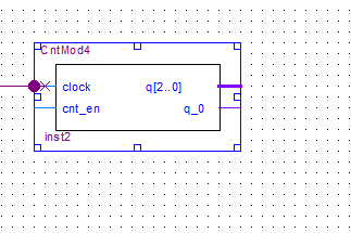
I don't quite follow. I'm assuming the node name needs to be set to address the bits since the interface does not have a wire symbol. https://www.alteraforum.com/forum/attachment.php?attachmentid=12011 What would I name CntModout to access q[0] for example. Do I have to do something in the symbol file? Thanks...Roger50310 LIBRARY ieee; USE ieee.std_logic_1164.all; LIBRARY lpm; USE lpm.all; ENTITY CntMod4 IS PORT ( clock : IN STD_LOGIC ; cnt_en : IN STD_LOGIC ; q : OUT STD_LOGIC_VECTOR (2 DOWNTO 0) ); END CntMod4; ARCHITECTURE SYN OF cntmod4 IS SIGNAL sub_wire0 : STD_LOGIC_VECTOR (2 DOWNTO 0); COMPONENT lpm_counter GENERIC ( lpm_direction : STRING; lpm_modulus : NATURAL; lpm_port_updown : STRING; lpm_type : STRING; lpm_width : NATURAL ); PORT ( clock : IN STD_LOGIC ; cnt_en : IN STD_LOGIC ; q : OUT STD_LOGIC_VECTOR (2 DOWNTO 0) ); END COMPONENT; BEGIN q <= sub_wire0(2 DOWNTO 0); LPM_COUNTER_component : LPM_COUNTER GENERIC MAP ( lpm_direction => "UP", lpm_modulus => 4, lpm_port_updown => "PORT_UNUSED", lpm_type => "LPM_COUNTER", lpm_width => 3 ) PORT MAP ( clock => clock, cnt_en => cnt_en, q => sub_wire0 ); END SYN;Honored ContributorTricky
I think I got going in the direction I want if there is not a better way https://www.alteraforum.com/forum/attachment.php?attachmentid=12012 by modifying the symbol file by adding q_0 unless there is a better way Roger50310 ENTITY CntMod4 IS PORT ( clock : IN STD_LOGIC ; cnt_en : IN STD_LOGIC ; q : OUT STD_LOGIC_VECTOR (2 DOWNTO 0); q_0 : OUT STD_LOGIC ); END CntMod4; ARCHITECTURE SYN OF cntmod4 IS SIGNAL sub_wire0 : STD_LOGIC_VECTOR (2 DOWNTO 0); COMPONENT lpm_counter GENERIC ( lpm_direction : STRING; lpm_modulus : NATURAL; lpm_port_updown : STRING; lpm_type : STRING; lpm_width : NATURAL ); PORT ( clock : IN STD_LOGIC ; cnt_en : IN STD_LOGIC ; q : OUT STD_LOGIC_VECTOR (2 DOWNTO 0); q_0 : OUT STD_LOGIC ); END COMPONENT; BEGIN q <= sub_wire0(2 DOWNTO 0); LPM_COUNTER_component : LPM_COUNTER GENERIC MAP ( lpm_direction => "UP", lpm_modulus => 4, lpm_port_updown => "PORT_UNUSED", lpm_type => "LPM_COUNTER", lpm_width => 3 ) PORT MAP ( clock => clock, cnt_en => cnt_en, q => sub_wire0, Q_0 => sub_wire0(0) );Honored ContributorIMO the better way is using only HDL and no schematics.
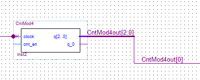
Anyway, in your problem you were close - you can just call the bus CntMod4out[2:0] and then from another wire you can just call it CntMod4out[0] to access bit zero.Honored ContributorTricky
So I could do something like.... https://www.alteraforum.com/forum/attachment.php?attachmentid=12014 I am wondering why you suggested that it would be better to use only HDL and no schematics. Are you suggesting don't use schematics at all in programing or create a block containing the HDL code to preform the action to access the counter bus and use that in the schematic. If you have any suggestions or questions please let know. Thanks for your help. Roger50310Honored ContributorYou leave the wire CntMod4Out[0] unconnected from CntMod4Out[2..0] - the fact that you have given it the same name will connect via named association. Conneting it like your picture will probably cause an error.
Schematics are problematic for several reasons: 1. You cannot simulate them (you need to convert to HDL first) 2. You cannot easily comment them 3. They are not portable between vendors. 4. They dont play nice with version control 5. They can easily become a mess 6. They dont always map nicely to HDL, and lack a lot of the features of HDL (parameterisation being the first). So given the above, it is usual that entire projects are done in HDL where possible, as none of the above problems apply.