Altera_Forum Honored Contributor
Honored ContributorHonored ContributorPlease check the attached image, why some signals are fuzzy?
They supposed should be clean "low" or "high" Many Thanks. https://www.alteraforum.com/forum/attachment.php?attachmentid=6697Honored ContributorYou will see this if the signals you are sampling are not synchronous to the signal tap II clock.
Basically you are sampling asynchronous signals. This can be useful if you want to see whether there is activity on signals in another clock domain, but its not very useful for tracing synchronous activity on signals. For that, you need to make sure your signal tap II clock is the same clock as used by the logic you are tracing. Cheers, DaveHonored ContributorSignalTap is based on digital logic, so it either captures a 1 or a 0. (It could go metastable, but that won't show up in the SignalTap waveform. And since captured data just feeds a large capture buffer, it's unlikely to cause any problems at all, since the fanout is probably 1 the whole way...)
The numbering on the top is your clock edge. Your sampling with a clock that is much faster than most of the signals, but when they transition a lot, it looks like that. Zoom in and you should see clean values for each clock. (Looks like you have a pretty deep buffer size...)Honored ContributorSorry, I have to use another username since I forgot the last one.
Many thanks for your explanation.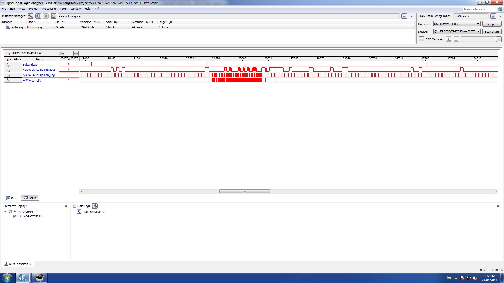