Serge93 Occasional Contributor
Occasional ContributorJTAG Chain Broken on Agilex 7-I Dev Kit
 Occasional Contributor
 Regular Contributor
Hi Serge93,
Thanks for reporting this. Please try these quick steps:
Please share your kit ordering code and the output of jtagconfig --debug after step 3.
Regards,
Fakhrul
Occasional ContributorHello Fakhul,
I already did all what you said including trying to access the board through the BTS. I was able to reconfigure the MAX10 by bypassing the FPGA but it changed nothing. The Agilex 7i is impossible to configure even with an external USB Blaster with reduced clock.
kit ordering code : AGIPCIe8100650 / N24193-001
The Result of jtagconfig --debug is :
[niosv-shell] C:\Users\serge\AppData\Local\quartus> jtagconfig --debug
1) AGI FPGA Development Kit [USB-1]
(JTAG Server Version 25.3.1 Build 100 12/19/2025 SC Pro Edition)
Unable to read device chain - JTAG chain broken
Captured DR after reset = ()
Captured IR after reset = ()
Captured Bypass after reset = ()
Captured Bypass chain = ()
JTAG clock speed auto-adjustment is enabled. To disable, set JtagClockAutoAdjust parameter to 0
JTAG clock speed 24 MHz
Thanks for help.
Serge
Regular ContributorHi Serge,
Thanks for the update. Could you try below:
You may refer to this user guide for the above steps: Agilex™ 7 FPGA I-Series Development Kit User Guide
If the chain is still broken with the FPGA in the path after the above, it suggests a board‑side JTAG issue, it can indicate a board integrity problem once power and connections are confirmed. We can proceed with RMA.
Please also share clear photos or a list of the current SW1–SW6/SW8 positions.
Regards,
Fakhrul
Occasional ContributorHello Fakhul,
So,
About (1) : I have set all the switches as asked, please see the picture attached.
About (2) : Unfortunately The LED D6 is Off.
About (3) : See the picture attached, I cannot communicate with the board, So I cannot get any voltage value.
About (4) : Please see the attached picture.
About (5): I had to use the J10 instead of J8 to be able to reconfigure the MAX10, otherwise I cannot get the JTAG chain and so I cannot configure the MAX10. I power cycle and the JTAG is still the same...
Thank you for your help.
Serge
Regular ContributorHi Serge,
Thanks for the updates:
1. May I know whether is this issue is first time and the board works ok before?
2. May I know which is your Ordering Code/Device Part Number? you may refer table below: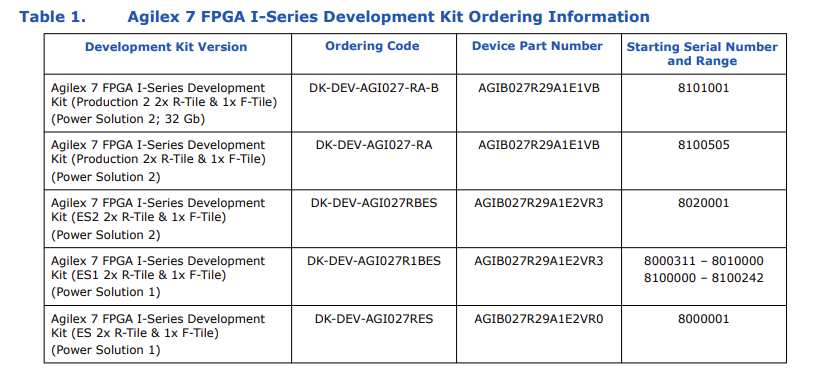
3. In Quartus programmer, could you click "auto Detect" and snap the device chain screenshot?
4. Could perform the following steps: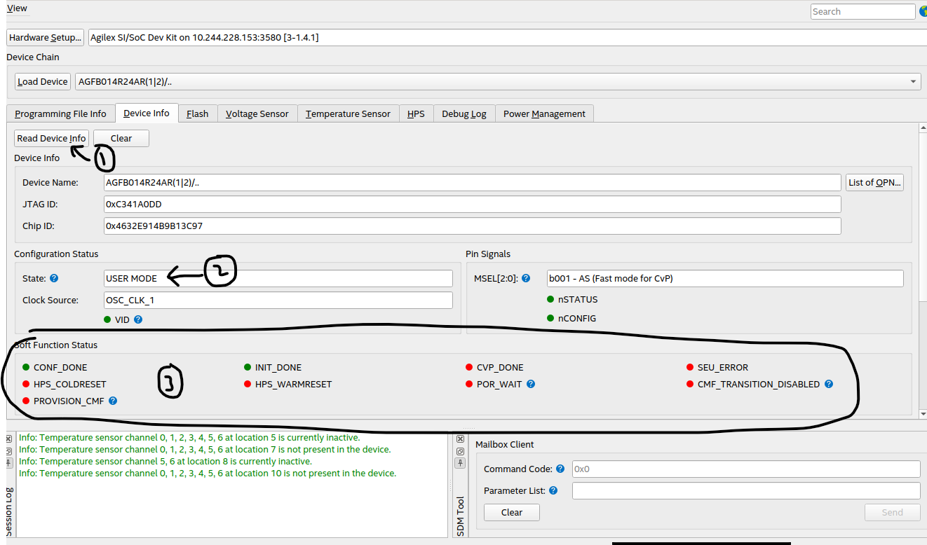
1- connect to board
2- go to Device info -> Read Device Info
3- observe Configuration Status -> State: ??
4- check the led color in Soft Function Status : green or red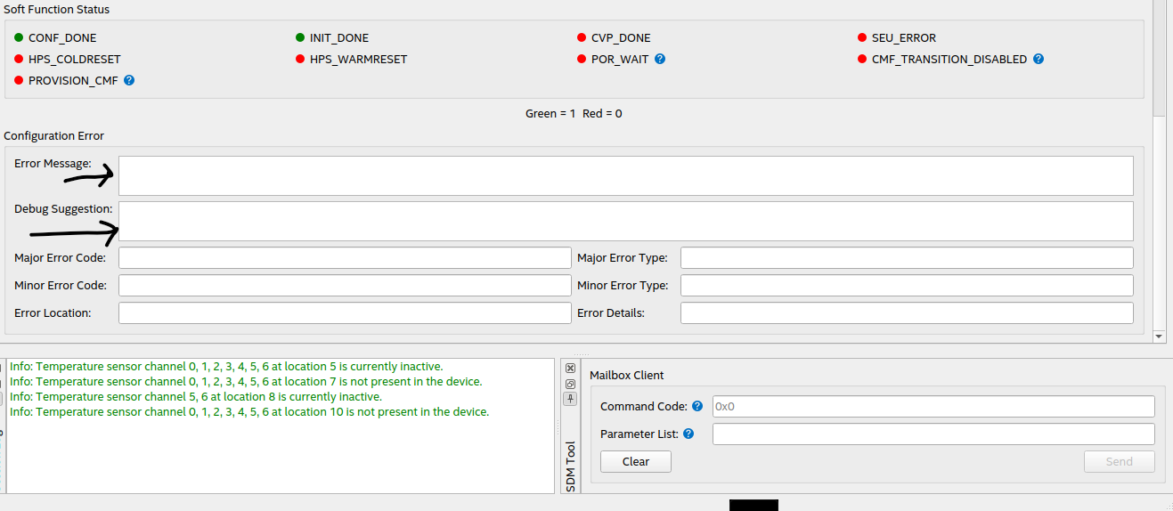
scroll down, can see Configuration Error -> Error Message -> Debug suggestion
5. Bench power only. Plug the 240 W adapter to J11, set SW6 = ON, keep the card out of any PCIe slot, cold power cycle. Does D6 turn blue?
Regards,
Fakhrul