
BrianSune_Froum Contributor
ContributorCyclone V SoC 5CSXC6 Series GXB Utilization and Limitations
 Contributor
 Contributor
LSS: The goal here is to find the possible usage or maximum usage on these GXB.
PCIe is a must the reduction to x2 is also good enough as x4 itself do not really gain much BW via HPS.
So if possible x4 on remain GXB is what we expected.
bottom [0|1] <- PCIe x2
bottom [2] + top[3|5] [4] ? 4 channel via fPLL x2 ??

 Regular Contributor
Hi,
Thank you for the update. Based on my understanding, you are planning to implement the following configuration:
From a theoretical standpoint, this configuration appears feasible. I would recommend creating a small test design and running it through the Fitter to verify compliance with any internal placement rules.
Please let me know if you have any questions or if there are any concerns. Thank you.
ContributorAgain I really want official answer on the actual placement validation.
For what I do a quick placement test it never work unless [CH3 CH5] only
The fitter report reconfiguration placement issue
It is very hard to trace the fitter issue from just a simple error message.
b.c. it never explain nor mention the actual resource tried to route is not feasible by what causes.
However based on our long discussions:
Question or original placement of PCIe IP block why require CH4 but not CH1 in the first place?
Without understanding this in the first place we can only guess it is not able to share CMU PLL
with TRX otherwise resources speaking why additional place CH4 not CH1 in the first place?
Next, channel placements are just a small part of the transceiver design w/o the reconfiguration
it cannot function as well.
So LSS: can it be as simple as a table that what is the possible combination of transceiver placements?
Thanks,
Brian
Regular ContributorHi Brian,
Thanks for your update. Please allow me some time to look into this observation "quick placement test it never work unless [CH3 CH5] only". I will provide you an update on the progress by end of this week or as soon as there is any valid finding.
Regular ContributorHi Brian,
Just to update you that I am still running tests using Native PHY designs to check the placement rules. Could you please share the test design that reproduces the reconfiguration placement issue? I would like to replicate the issue on my side and continue debugging from there.
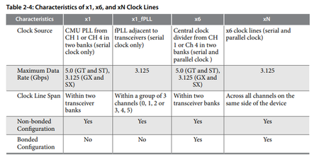
Regarding your question on “why the PCIe IP requires CH4 instead of CH1 in the first place”: If I understand you correctly, you are asking why, in PCIe x2 mode, CH4 RX is required as the CMU PLL. If so, for clarification, the CMU PLLs in CH1 and CH4 also function as the CDRs. When PCIe x2 uses CH0 and CH1, there is no additional CMU PLL available in CH1. As a result, the design must use the CMU PLL in CH4.
Please let me know if I misunderstood your question or if you need any further clarification. Thank you.
ContributorI can only share the IP from altera all other logic and block will be cropped if this is ok for you I will cont'd to do so.
Q: I think the major issue here is reconfiguration block 1 -> top 1->bottom only 1 on each.
so if the reconfiguration block already hold by PCIe there is not way additional transceiver can run on different speed unless it is same as PCIe spec.
So before we spend time on this maybe have a look on Q:
I am not sure you are altera FAE staff or just regulator forum contributor?
However, I think if you have idea have to do it you should able to use this to validate what we are discussing.
Fair enough for my side to provide this and I cannot see why there are no easy test on your side to validate this as well.
Thanks,
Brian
Regular ContributorHi Brian,
Thanks for your update. Sure, let me take a look into your latest Q before we decide on the next step of debugging.
Regular ContributorHi Brian,
For your information, I have created a test design with the following configuration, and it successfully passes Fitter compilation:
From my observation, only one reconfiguration controller can be instantiated in the design. This is likely due to the fact that there is only one calibration block in the CV device. This would also explain your earlier observation—when more than one reconfiguration controller is included, it results in compilation issues.
Please let me know if you have any questions or concerns. Thank you.
ContributorYou are just repeating what I had done.
This is making no sense, what I am asking is that can or could it possible to use PCIex4 with 2 custom phy in any form of configuration.
BTW I had successfully fitter top with individual recfg controller. On PCIe X2 case so please try it yourself.
This had violate what you had concluded.
Regular ContributorHi Brian,
Thank you for the update. I’m glad to hear that you’ve successfully fit the bank with PCIe x2, three duplex channels, and one TX-only channel.
Regarding your latest question on using PCIe x4 + two custom PHYs, could you please confirm whether the custom PHYs are full duplex? If they are, based on Figure 4‑5: 12 Transceiver Channels and 2 PCIe HIP Blocks with PCIe x2 and x4 Channel Placement in the Cyclone V Device Handbook, Volume 2: Transceivers, CH0–CH3 would be occupied by PCIe x4, with the CMU PLL sourced from CH4. In this configuration, there would not be sufficient resources to accommodate two additional full-duplex custom PHYs.
Regarding the reconfiguration controller, apologies for the earlier confusion, and thank you for pointing it out. To clarify, in Cyclone V devices, a maximum of one reconfiguration controller is allowed per transceiver bank (three transceiver channels).
Please let me know if you have any questions. Thank you.
ContributorI want your test project to cross check the setup of your full-duplex is align with what we are expecting.
That you placed 3 custom duplex and 1 TX with 2 channel PCIe, I think there is sometime not aligned.
Thanks,
Brian
There is still an issue on CH4 where you claim you had successfully fitter TX on that channel.
However this is unable to achieve from beginning to current state:
Where either CH2 CH3 CH5 also good to place whatever custom design.
So how you actually constraints or what settings are done to make this possible?

