Altera_Forum Honored Contributor
Honored ContributorHonored ContributorHonored ContributorI like the ingenuity of using standard board layout and geometries to mount a Micro-BGA package. Nice thinking.
As for the problem - TDO should be high when not active. So, I would expect an unprogrammed part to show a logic high (3.3V in your case). 0V indicates a problem. User I/O pins of an unprogrammed device should be high impedance. So, I don't believe shorting TDO to these pins should be a problem. Connect TDO to lots and it might be. However, you only appear to be shorting it to two additional pins. I think this should be fine. I assume these pins aren't used once the CPLD is programmed and they remain high-impedance? I assume you can't detect the CPLD? Have you (or can you) Xray the boards? I suspect a manufacturing issue - either with the assembled board or the bare PCB. A solder splash or perhaps some compromised solder resist. You appear to have some sort of copper flood - although it's difficult to tell what layers you have displayed. How near is any copper at 0V? Cheers, Alex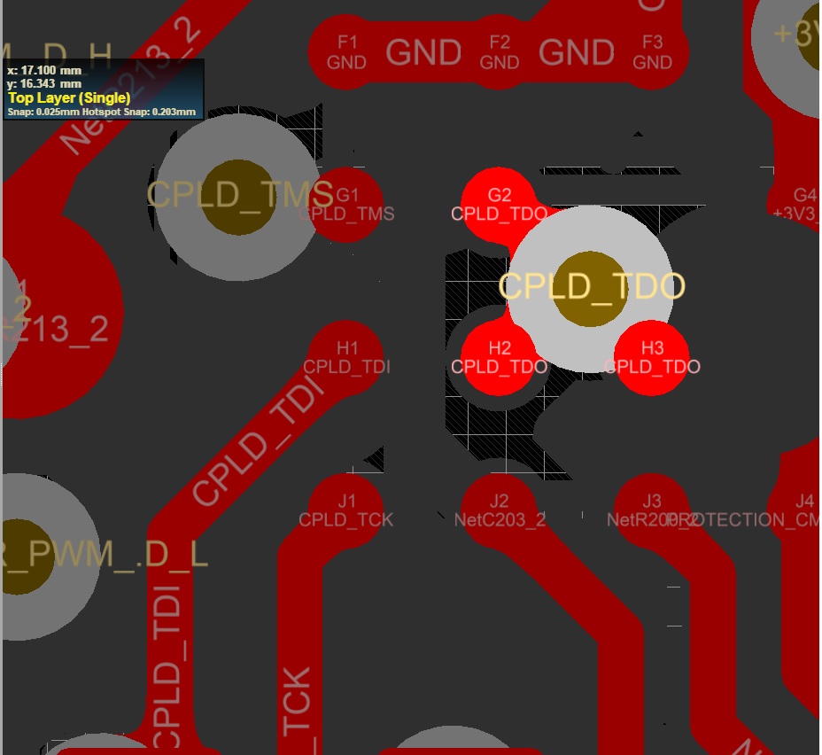