Forum Discussion

 Occasional Contributor
Agilex 7 F/I Series True Differential Input Termination
 6 months ago
Hi Steve,
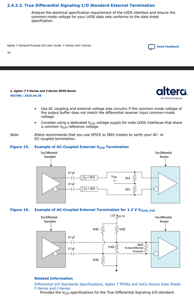
reviewing documents and reference design, I agree that GPIO manual, datasheet and development kit schematic are inconsistent in several regards. Looking also at IBIS file, there seems to be a non-linear pull-up feature for TDS input standard which effectively pulls Vicm to about half supply with applied signal. Not sure if IBIS input characteristic is real or roughly simplified.
So all-in-all, it seems like development kit implementation is a possible minimal effort termination option.Regards
Frank
 Occasional Contributor
Thanks. this is the dev kit I was referring to. It looks like the following differential pairs into the FPGA fabric are AC coupled with no external bias. There are bias resistors that are DNI'd on schematic/BOM so they are not installed. What do you think about those? If that was done on the dev kit it made me think AC coupling w/ no bias was acceptable.
ToD_MASTER_CLK_125M_P/N
PTP_SAMPLE_CLK_250M_P/N
https://www.intel.com/content/www/us/en/content-details/843994/agilex-7-fpga-f-series-development-kit-production-1-2x-f-tile-revd-dk-dev-agf023fa-development-kit-board-schematic.html
 Super Contributor
Hi Steve,
reviewing documents and reference design, I agree that GPIO manual, datasheet and development kit schematic are inconsistent in several regards. Looking also at IBIS file, there seems to be a non-linear pull-up feature for TDS input standard which effectively pulls Vicm to about half supply with applied signal. Not sure if IBIS input characteristic is real or roughly simplified.
So all-in-all, it seems like development kit implementation is a possible minimal effort termination option.
Regards
Frank
- Steve96 months ago
Thanks Frank.
Yes the documentation was not clear to me w/ regard to AC coupling/internal biasing.
I was able to get my hands on an Agilex -7 F series board and took some measurements of an AC coupled LVDS input. In this case the internal OCT was not enabled and there was an external 100 ohm termination resistor present on the Agilex side of the series AC coupling caps.
With no bias resistors at all on Agilex side of AC coupling caps: A single leg oscillated ~940mV to ~1.17V. So common mode of 1.055V and VID of 0.21V.
With a 10k pullup to 1.2V and a 10k pull down to GND on each leg (so should set a 0.6V bias for each leg: Swing of a single leg was from ~480mV to ~720mV. So Common mode of ~0.6V and swing of ~0.24V
 AqidAyman_Altera6 months ago
Regular Contributor
Hi Steve,
May I know if you have additional question on this?
- Steve95 months ago
I am all set here thanks! Sorry for the delay, I marked Frank's reply as the solution.


