Forum Discussion

 Occasional Contributor
Very slow clock should be constraint as false path?
 2 years ago
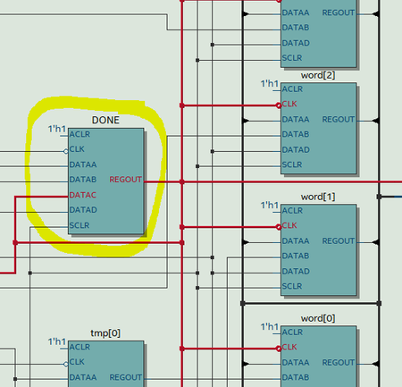
The problem is that you are using DONE as a clock signal. It's not. You should just create combinatorial logic or better yet synchronize the loading of word with clk.
always @(negedge clk) begin
   if (reset) begin
       word<=0;
   end
   else if (DONE && clk_enable) begin
       word<=tmp[7:0];
   end
end
 Occasional Contributor
Hi Sstrell
1-"You could use a counter to keep track of a signal level for multiple clock cycles"-->that not sure how, my FSM is sampling the 1200baud data for each 1200Hz clock enable pulse (one 50MHz clock every 1200Hz) .
2-"Or you could use a multicycle timing exception to have the timing analysis extended an extra cycle if you can't change the design"-->in my case as u see my capture window is half 50Mhz clock, FSM samples on rising edge and capturer on falling edge, so cannot apply multicycle between both modules.
JFYI let u the simple FSM code, u can see what i mean.. For your porpossal might need to modify FSM increasing number of states it stays as GO=0 and GO=1, sampling several clock cycles like a sequence detector, ie: detect 2 zeroes triggers start bit then move to state RUN...?. Of course would need also to enlarge the clock enable width for the appropiate window... lets say... 4X50MHz clk´s each 1200Hz...
Now FSM is just simple IDLE<-->RUN...
As u see im just trying to learn and enhace, even timing is acceptable around 112MHz, slack is also ok...
Thanks for your share and time in advance!.
BR
 Super Contributor
some improvements suggested. Presume rs232 input data is asynchronous to FSM clock. Then a certain rate of FSM failure must be expected, worst case a non-recoverable transition to an illegal state. It's necessary to add a synchronizer register chain for data.
- Armando19892 years agoHello FVM
No worries, rs232 input signals are pass trough 2 flop synchronizers, just are spare modules outside.
Br


