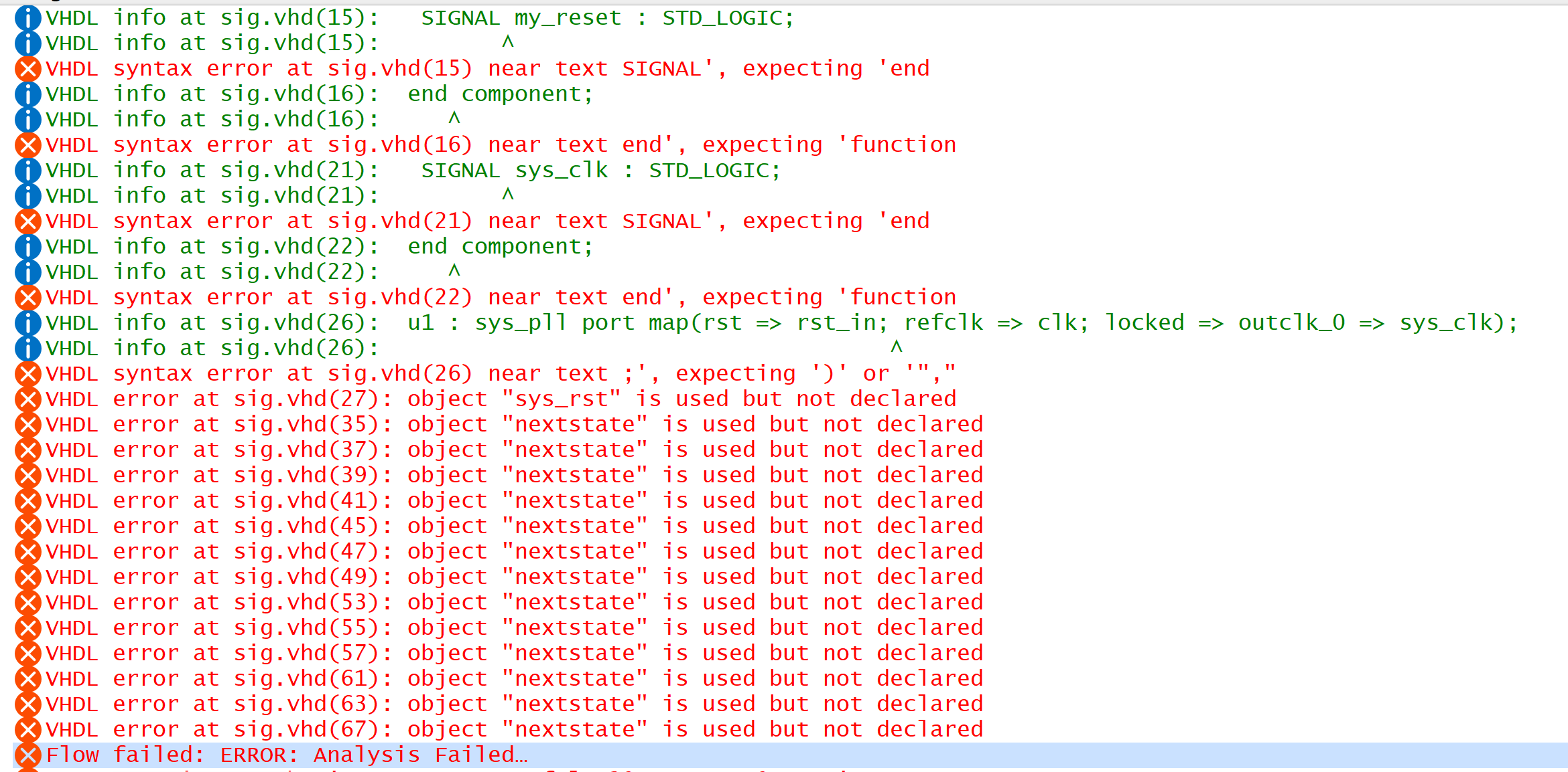
You don't show what errors you're getting now, but here are the many issues I see:
Where is the code for component clockdiv?
Why does sys_pll.vhd have a signal in its port list named my_reset? I presume you added this in for some reason. Assuming this is generated from an IP, you should not be editing the top-level code for the IP. In the IP Parameter Editor, you should go to Generate -> Show Instantiation template and use the template there to instantiate the IP exactly as it's generated. There is no reason to edit the top-level code for a generated IP. For a basic PLL, there are only 4 signals: refclk and rst inputs, and locked and outclk_0 outputs. What are sys_clk and rst_in since there is already outclk_0 and rst? And why is locked bidirectional? It's an output status signal from the PLL. And there is no bidirectional logic in the core of an FPGA. The component declaration should simply be (from the instantiation template):
COMPONENT sys_pll is
PORT (refclk, rst: IN STD_LOGIC;
locked, outclk_0: OUT STD_LOGIC);
END COMPONENT;
ninit_done is an output of the reset release IP and yet you are connecting it to an input port in the toplevel, an input pin of the device, which makes no sense. It should be connected to reset inputs of the instantiated components or used as a status indicator. And what is sys_rst supposed to be doing? You declare it and then it's not used anywhere. The reset release IP should be used as just a status indicator that device initialization is complete. You can use it as a reset signal, but it won't ever go low again during normal operation of the device so it can't be used as a warm reset.
If you're not using the locked signal of the PLL, just leave it out of the port map. You're basically connecting a signal to itself when you say locked => locked, which makes no sense.
Speaking of port mapping, you have it backwards for the PLL. The first signal name is the name of the component's port. The signal after "=>" is the signal in this level of the design that the lower-level port is connecting to. So your PLL instantiation should probably look like this:
u1: sys_pll PORT MAP (rst_in => my_reset, clk => clk, outclk_0 => iclk);
Even this isn't perfect because what is the point of clockdiv? You can divide a clock using the PLL itself instead of needing oclk and iclk.
I highly suggest you check out some VHDL training: https://cdrdv2.intel.com/v1/dl/getContent/652842
 Occasional Contributor
 2 years ago