Forum Discussion

Altera_Forum Honored Contributor
8 years agoHonored ContributorPISO reg issue
Hello there.
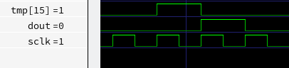
I am trying to implement PISO register with this code (dout and tmp are regs)
always @(posedge sclk)
begin

    if (cs == 0)
    begin
        dout <= tmp;
        tmp <= { tmp , 1'b0 };
    end
end
4 Replies
 Altera_Forum
You're using non-blocking assignments. Thus the first assignment is using the "old" value of tmp[15] from the previous cycle. Use blocking assignments (= instead of <=).
- Altera_Forum
That was helpful!
But i faced another problem with those shift regs :c
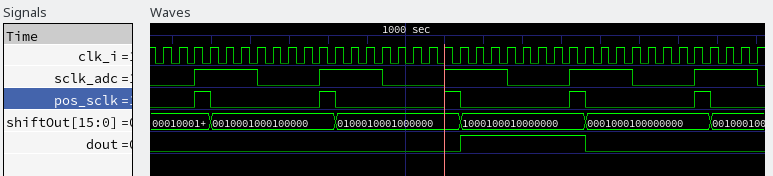
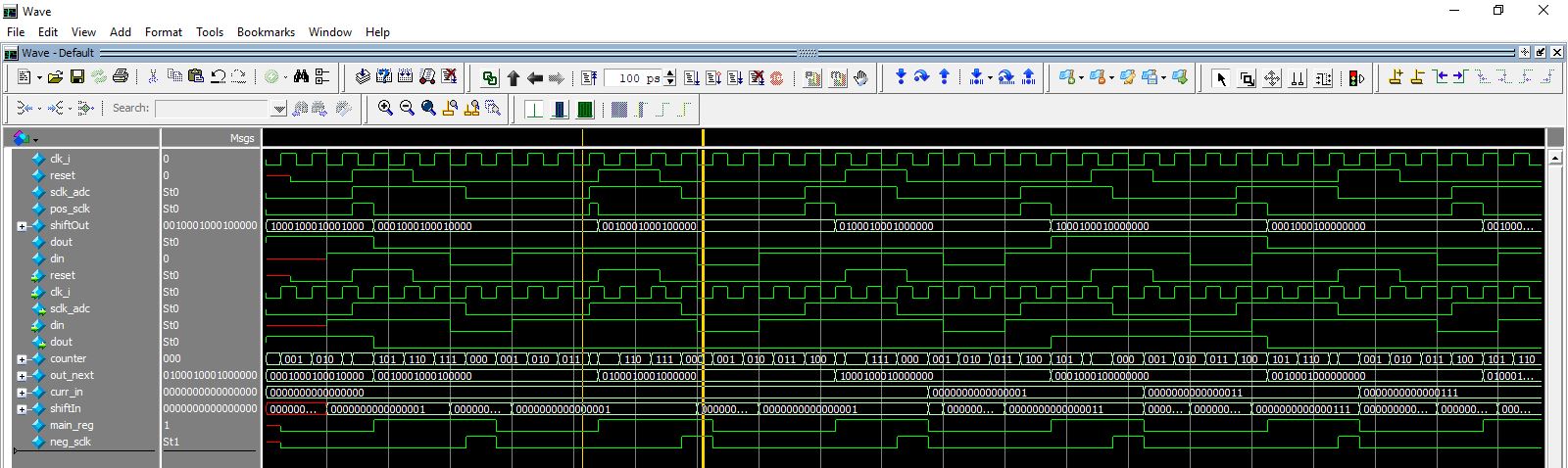
So, i generated slow clock sclk_adc from main clock, and then need to load regs within posedge and negedge of this sclk_adc. If i simply wrote if (sclk_adc) ... else... my shift regs will load with main clock since this block is posedge clk_i, so i created pos and neg edge detectors which work well enough, but they latched on the next clk after pos_sclk detected, why? in this matter change in block/non-block assignments does not affect answer. pls help me to explain this is there any way to avoid creating a new always (with sclk_adc event there) blocks? https://www.alteraforum.com/forum/attachment.php?attachmentid=15845module shiftreg1 ( input reset, input clk_i, output sclk_adc, input din, output dout ); reg counter = 0; reg shiftOut = 16'b1000_1000_1000_1000; wire out_next; // assign sclk_adc = counter; reg curr_in = 0; wire shiftIn = {curr_in, din}; assign dout = shiftOut ; assign out_next = { shiftOut, 1'b0}; reg main_reg; wire pos_sclk, neg_sclk; assign pos_sclk = sclk_adc & ~main_reg; assign neg_sclk = ~sclk_adc & main_reg; //////////////////////////// always @(posedge clk_i or posedge reset) begin counter <= counter +1; main_reg <= sclk_adc; if (pos_sclk) begin shiftOut <= out_next; end if (neg_sclk) begin curr_in <= shiftIn; end end endmodule - Altera_Forum
Hi,
--- Quote Start --- If i simply wrote if (sclk_adc) ... else... my shift regs will load with main clock since this block is posedge clk_i, so i created pos and neg edge detectors which work well enough, but they latched on the next clk after pos_sclk detected, why? --- Quote End --- It seems to be latched on the next clk after pos_sclk detected but if you check carefully the posedge clk_i & posedge reset wave then you we will reliase that it is looking for posedge clk_i or posedge reset event when pos_sclk is High. Refer the yellow colored cursor portion in the attached screenshot. Let me know if this has helped resolve the issue you are facing or if you need any further assistance. Best Regards Vikas Jathar (This message was posted on behalf of Intel Corporation)  RKing1
New Contributor
thanks a lot guys for answering the questions. i really find it very useful but i was wondering if you could answer some of my questions as well? please? anyway thanks for anything so far!