--- Quote Start ---
Your problem and image is not very clear, but it is most likely a code or testbench problem rather than a bug.
--- Quote End ---
Then I will provide more information here:
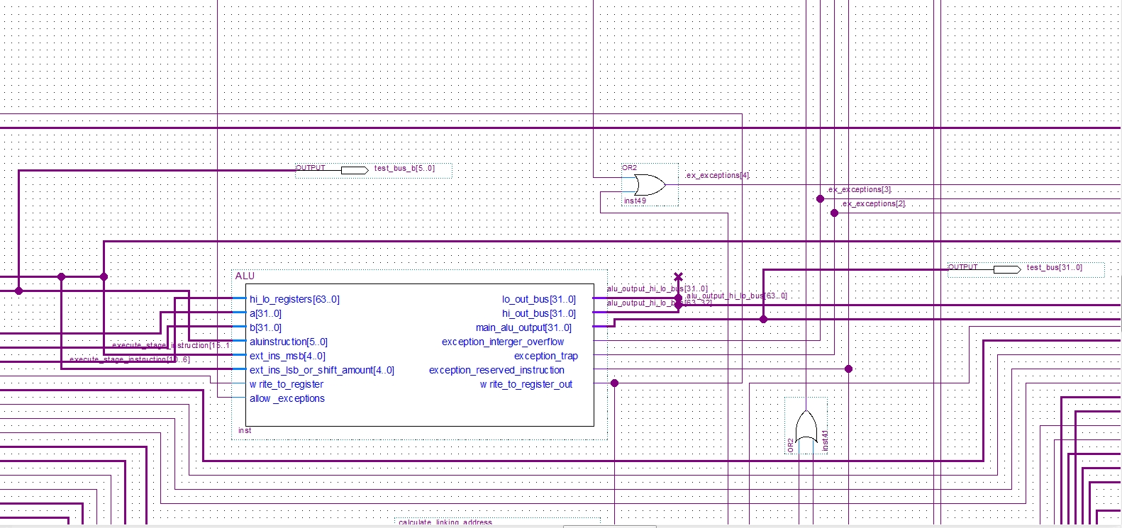
This is how the 2 test pins are connected to the ALU in schematic design:
https://www.alteraforum.com/forum/attachment.php?attachmentid=6636 As you can see they are connected directly to the input and output of the ALU. The ALU itself has no latches and it is entirely sequential. Too me it looks like it is some sort of bug since the ALU was working completely fine before. I was using it before and I never had any sort of problem like that. I also did not have those X values either.
Edit: I would like to do a gate level simulation instead of RTL however I can't as my design has more pins then my FPGA can support.
EDIT: I figured out the issue since I managed to figure out how to probe internal values. The issue was that Modelsim messed up an internal signal. My adder unit code is this:
library IEEE;
use IEEE.STD_LOGIC_1164.ALL;
use IEEE.NUMERIC_STD.ALL;
entity alu_adder is
port (
		input_a: in  std_logic_vector(31 downto 0);
		input_b: in  std_logic_vector(31 downto 0);

		subtract: in std_logic;
		ignore_overflow: in std_logic;

		output: out std_logic_vector(31 downto 0);

		overflow: out std_logic
     );
end alu_adder;
architecture Behavioral of alu_adder is
signal adder_output: std_logic_vector(32 downto 0);
begin
process(input_a, input_b, subtract, ignore_overflow)
begin
output <= adder_output(31 downto 0);
overflow <= '0';
if subtract = '1' then
adder_output <= std_logic_vector(signed(input_a(31) & input_a) - signed (input_b(31) & input_b ));
else
adder_output <= std_logic_vector(signed(input_a(31) & input_a) + signed (input_b(31) & input_b ));
end if;
if ignore_overflow = '0' then
if adder_output(32) /= adder_output(31) then
overflow <= '1';
end if;
end if;
end process;
end Behavioral;
It turns out I had to add the adder_output signal to the process list. All of the Xs also disappeared. Pretty weird for it to do that.
 Honored Contributor