Forum Discussion

 Occasional Contributor
Stratix 10M DIB Module
 3 years ago
Hi,
I cannot seem to get engineering to confirm the values, but the normal practice is by adjustment.
You can start with the values they put for the example design and fine tune it after compilation.
Below are the values used:
- max C=2.65
- min C=-2.65
- max A + max B = 8.25
- min A + min B = 3
- max D + max E = 4.75
- min D + min E = -1.64
Regards,
Nurina
 Regular Contributor
Hi Or,
- The clock should be virtual clocks, so there shouldn't be a target. You just need to define the period and name of the clock and Timing Analyzer will create a virtual clock.
- What do you mean by system synchronous, how is it different from your source synchronous design?
- The B,C,D timing values from Figure 16 of the above document is as follows. B=D=DIB Latency=2.5ns as mentioned here https://www.intel.com/content/www/us/en/docs/programmable/683142/20-2-19-3-0/latency.html. EMIB Delay=C=Wire Delay of Stratix 10
- The set_input/output_delay should be targeting the virtual clocks and the ports connected to DIE1_dib_pad_2_22*
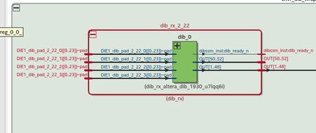
- <<my understanding that the input from the EMIB inserted to the Die1 via DIE1_dib_pad_2_22_2[18] , dib_0 module does nothing in bypass mode (just routing) , and the OUT[18] is the continuation of the wire .>> Is this specific to your design? If not, then you may apply the timing constraints as suggested above.
There is a DIB IP example design, you can generate this in the Platform Designer. You may refer to this example design for the timing constraints.
Regards,
Nurina
 Occasional Contributor
Hi Nurina
- Clock should be assign to IO – when constraining Source Synchronous interfaces
Look at this training and document and trainings from Intel/Altera.
Slide 12,27
https://cdrdv2-public.intel.com/653688/an433.pdf
Section Output Clock Constraints and Input Clock Constraints
- in System Synchronous – the clock is not transferred with the Data (as in Source Synchronous) – in system Synchronous the clock is transferred to both devices , and should be aligned.
- where can I find “EMIB Delay=C=Wire Delay of Stratix 10” Values , I search and find nothing about it . which document describes it ?
Searching for EMIB in this document finds nothing.
- This is not accurate according to “Source Synchronous interface “ - see course and document above .
The output delays of the “Transmitting Device “ is assign to the clock which defined on the output Pin . / Slide 26 ,31 at the training
For the Receiving Device ,you are right, the input delay is according the virtual clock .
- This is not specific from my implementation this is Module I get when I generated the DIB module .


