Forum Discussion

OrF Occasional Contributor
3 years agoOccasional ContributorStratix 10M DIB Module
Hi
I'm using the DIB to inter connect between the 2 dies of the Stratix 10
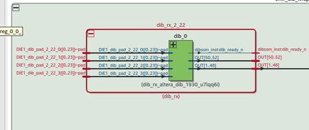
I'm using it in BYPASS (therefore I need to define the constraints) mode and one of the IO is transferring clock from ...
 3 years ago
Hi,
I cannot seem to get engineering to confirm the values, but the normal practice is by adjustment.
You can start with the values they put for the example design and fine tune it after compilation.
Below are the values used:
- max C=2.65
- min C=-2.65
- max A + max B = 8.25
- min A + min B = 3
- max D + max E = 4.75
- min D + min E = -1.64
Regards,
Nurina
Nurina Regular Contributor
3 years agoRegular ContributorHi,
Please refer to this document for timing constraint guideline: https://www.intel.com/content/www/us/en/docs/programmable/683142/20-2-19-3-0/timing-transfer-for-bypass-mode.html
Regards,
Nurina
 OrF3 years ago
I'm aware of this document ,
The document leaves many open questions , and does not refer to my questions.
- The document is talking about system synchronous and not Source synchronous as my case.
- I didn't find any place that specifies the values of B,C,D Timing values (at the Figure 16) the only timing which was specifies is 2.5ns, it is not written if 2.5ns = EMIB Delay (C values) , or the DIB Latency (B,D values) - or all the values together .
- My question was to where should I set the input/output delays practically in the SDC, which means to which pins or ports?, it is not written in the document , what is the dib_0 module (in my original question) stand for , is it the "Die B DIB" (at figure 16)? or it is " EMIB+DIE B DIB " ?
- The importance of item 3 above is to understand if quartos timing analyzer , takes into account the internal routing of dib_0 and derived the clock definition in the input side and add the Routing delay inside the dib_0 module
Thanks
Or


