Altera_Forum Honored Contributor
Honored ContributorHonored ContributorHi,
Anyone know about the maximum current strength supported by pin SDI_HSMC_CLK(input) for SDI HSMC daughter card? In Quartus II Pin Planner, the default current strength of HSMC connector(HSMB_CLK_OUT_P2) to that pin is 12mA, but I have checked the datasheet of the FemtoClock™ Dual VCXO Video PLL (IC 810001-21), the maximum input high current is 150uA. The default current strength exceeds the current value which is stated in the datasheet (attachment), will it damage the IC? Thanks.Honored ContributorNo, it won't damage the IC.
150uA is the maximum current the device will draw when powered under the conditions stated. Just make sure you have the appropriate I/O standard selected for 'HSMB_CLK_OUT_P2' in the I/O planner. Reduce the drive strength right down and increase it if the wave shape at the receiver looks a little tired. Cheers, AlexHonored ContributorHonored ContributorHonored ContributorBy increasing the drive strength you will be improving (in your design) the wave shape at the receiver. This is clearly having a positive effect on your design.
Cheers, AlexHonored ContributorIt would be good to do signal integrity simulation to select the optimal drive strength for your setup. Lower drive strength will have slower edges. Higher drive strength might get more reflection. Need to balance between.
Honored ContributorFor more precious simulation result, you can also try Hspice model if you have the simulator.
Honored ContributorHonored ContributorThanks, Alex :)
Honored Contributor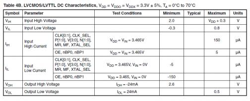